DUMP BODY
Removal
Inspect all lifting devices. Slings, chains, and/or
cables used for lifting components must be in-
spected daily for serviceable condition. Refer to
the manufacturer’s manual for correct capacities
and safety procedures when lifting components.
Replace any questionable items.
Slings, chains, and/or cables used for lifting com-
ponents must be rated to supply a safety factor of
approximately 2X the weight being lifted.
When in doubt as to the weight of components or
any assembly procedure, contact the Komatsu
area representative for further information.
Lifting eyes and hooks should be fabricated from
the proper materials and rated to lift the load being
placed on them.
Never stand beneath a suspended load. Use of guy
ropes are recommended for guiding and position-
ing a suspended load.
Before raising or lifting the body, be sure there is
adequate clearance between the body and over-
head structures or electric power lines.
Be sure that the lifting device is rated for at least a
45 ton capacity.
1. Park truck on a hard, level surface and block all
the wheels. Connect cables and lifting device to
the dump body and take up the slack as shown in
Figure 3-1.
2. Remove mud flaps and rock ejectors from both
sides of the body. Remove electrical cables, lubri-
cation hoses etc. attached to the body.
3. Attach chains around upper end of hoist cylinders
to support them after the mounting pins are re-
moved.
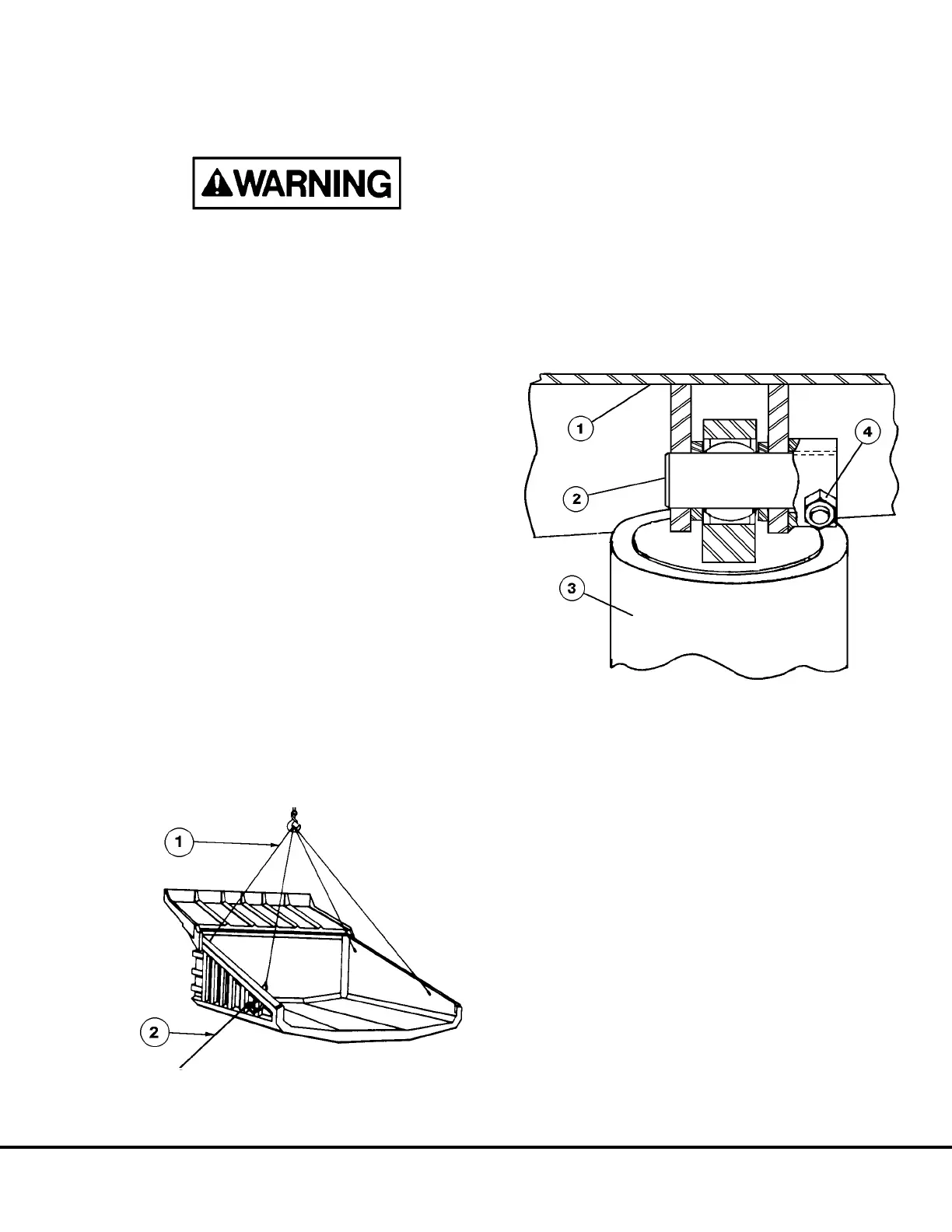
4. Remove pin retainer capscrew (4, Figure 3-2) from
each of the upper hoist cylinder mounting eyes.
With adequate means of supporting the hoist cyl-
inders in place, remove each of the mounting pins
(2, Figure 3-2).
5. Remove capscrews (2, Figure 3-3) and lock wash-
ers (3) and retainer (1) from each pivot pin.
6. Remove capscrews (4, Figure 3-3) and lock nuts
(5) from each pivot pin.
7. Attach a body pivot pin support fixture to bracket
on underside of dump body to aid in supporting
the pin as it is removed.
Remove body pivot pins (6) far enough to allow
shims (9) to drop out. Complete removal of pins
is not necessary unless new pins are to be in-
stalled.
8. Lift dump body clear of the chassis and move to
storage or work area. Block the body to prevent
damage to the body guide etc.
9. Inspect bushings (8, 11, & 12), body ear (7), and
frame pivot (10) for excessive wear or damage.
90909
FIGURE 3-1. DUMP BODY REMOVAL
1. Lifting Cables 2. Guide Rope
90444
FIGURE 3-2. HOIST CYLINDER MOUNT (UPPER)
1. Dump Body 3. Hoist Cylinder
2. Hoist Cylinder Pin 4. Pin Retainer
B03013 03/01 Dump Body B3-1