6. Install clamps (17) on cover rings (9). Tighten
clamps just enough to hold covers in place.
7. Charge front suspension as described in “Oiling
and Charging Procedure”, Section “H”.
8. Charge rear suspensions with nitrogen to fully
extend pistons.
9. Remove blocks or stands from beneath the frame.
10. Release nitrogen from rear suspension and
charge according to procedure in “Oiling and
Charging Procedure”, Section “H”.
Before removing blocks from the wheels, make
sure parking brake is applied.
11. Remove blocks from wheels.
PIVOT EYE BEARING
Disassembly
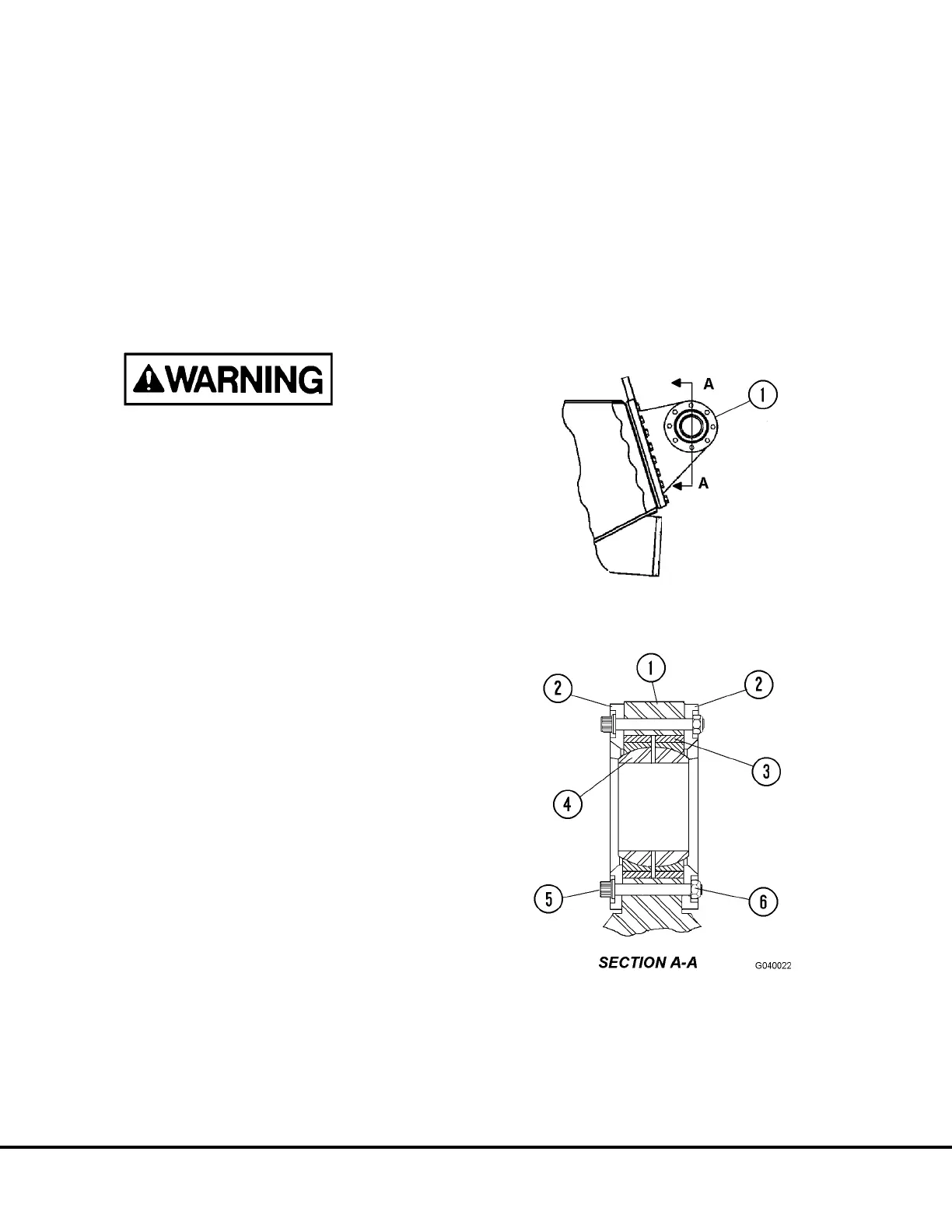
1. Remove capscrews and locknuts (5 and 6, Figure
4-2). Remove bearing retainers (2). Setup an
appropriate tool to press spherical bearing (4)
from bearing carrier (3).
2. Inspect all parts and bearing for wear or damage.
Replace parts showing excessive wear or dam-
age.
Spherical bearing outer race O.D.:
8.7500 - 8.7488 in. (222.25 - 222.22 mm)
Bearing bore I.D.:
5.9990 - 6.0000 in. (152.37 - 152.40 mm)
3. If bearing carrier (3) is damaged or worn, refer to
“Pivot Eye Repair” for repair procedure.
Assembly
1. Setup an appropriate tool to press spherical bear-
ing (4, Figure 4-2) into bearing carrier (3). Be
certain bearing outer race is flush with bearing
carrier sides.
2. Install bearing retainers (2) with 12 point cap-
screws (5) and locknuts (6). Tighten capscrews
to 575 ft. lbs. (779 N.m) torque.
FIGURE 4-2. PIVOT EYE BEARING
INSTALLATION
1. Pivot Eye Structure
2. Bearing Retainer
3. Bearing Carrier
4. Spherical Bearing
5. 12 Pt. Capscrew
6. Locknut
G4-2 Rear Axle Housing Attachment G04014
 Loading...


