Subcode 07:
Description: A low DC bus voltage was detected after
the phase controller power up sequence.
1. Check the 3-phase input connections and fuses
F1 and F2.
2. If no problem was found in step 1, use an ohm-
meter to check for short circuits between AM101,
AM201, and AM301 wires and between IV+ and
IV-.
3. If no problem was found in step 1 or 2, replace the
controller.
Subcode 08:
Description: A low DC bus voltage was detected
during operation.
1. Check Capacitor Bank and Controller connec-
tions.
2. Check DC Sense connection (connector J13 to
IV+ (red wire) and IV- (black wire)).
3. If problem still exists, replace controller.
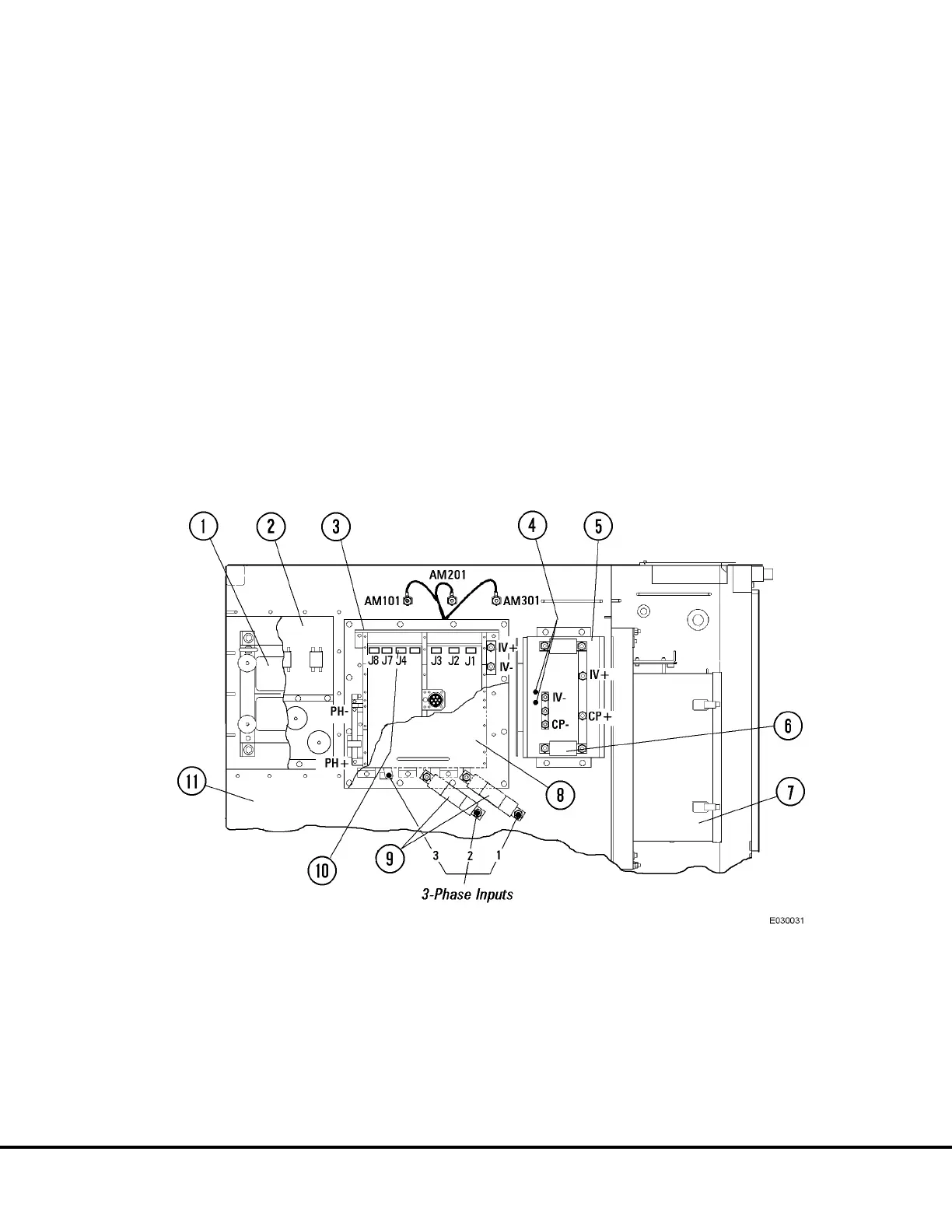
FIGURE 3-15. AUXILIARY BLOWER CONTROL COMPONENTS
1. Auxiliary Inductor (AXIND)
2. Snubber (AUX SNUB)
3. Auxiliary Inverter (Controller -AXINV)
4. Blower Control System Warning LED’s
5. Auxiliary Power Filter Capacitor Bank (AXCAP)
6. Capacitor Fuses
7. Propulsion System Controller (PSC)
8. Cover
9. Input Fuses (F1 & F2)
10. 3- Pin Connector
E03015 3/01 AC Drive System Electrical Checkout Procedure E3-39
(Release 17 Software)
 Loading...


