Regulator Bypass Test
If the test procedure outlined on the previous page
indicates low current output
and
low voltage out-
put, perform the following test to determine if the
voltage regulator is defective or if the alternator is
defective.
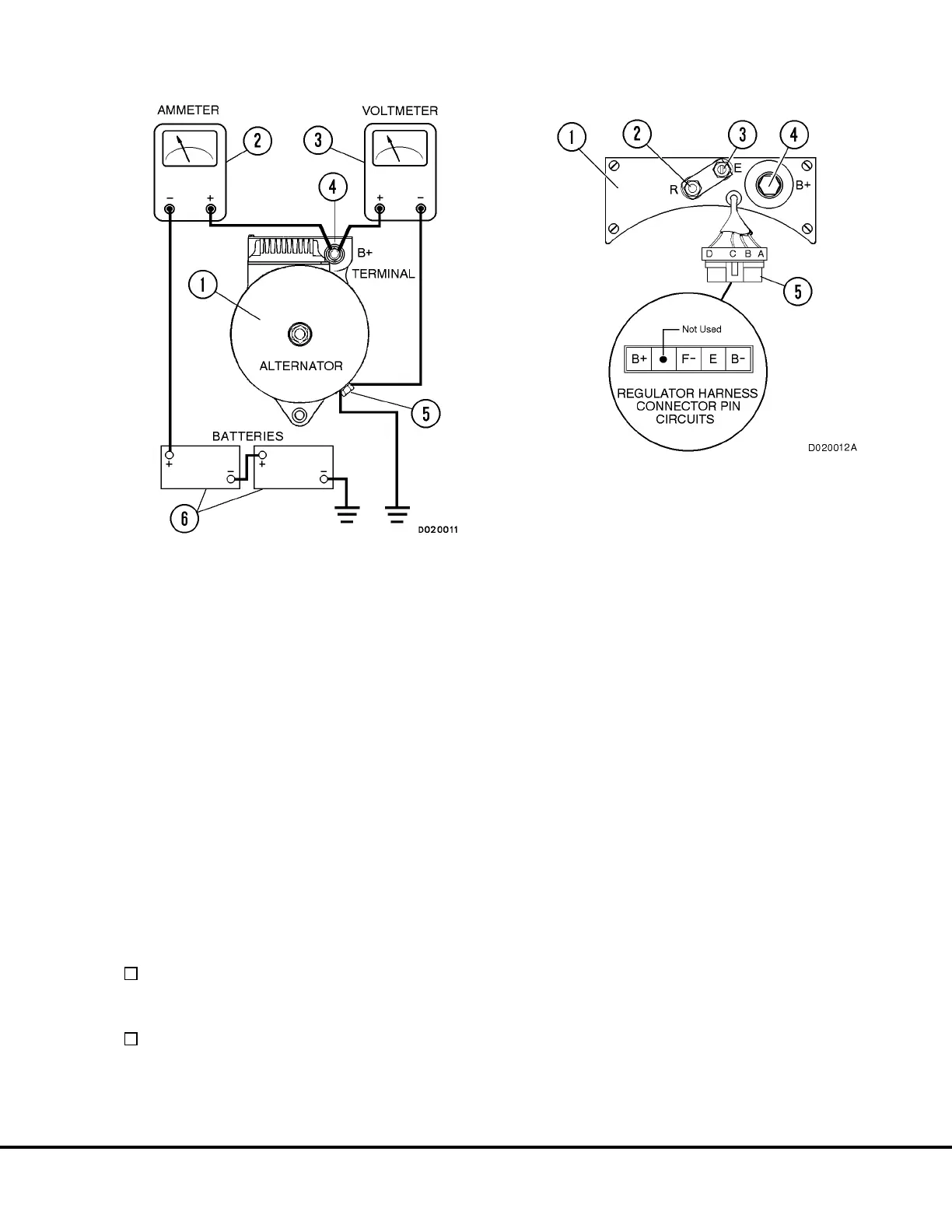
1. Disconnect alternator/regulator harness plug (3,
Figure 13-3).
2. Momentarily touch the “F-” connector pin on the
alternator connector to ground.
3. Observe meter readings:
If voltage or amperage rises, the alternator is
OK. The regulator is defective and should be
replaced.
If grounding the harness male pin has no effect,
the alternator is defective and should be re-
placed.
FIGURE 13-2. TEST METER HOOKUP
1. Alternator Under Test
2. 0 to 400 AMP Ammeter
3. 0 to 40 VDC Voltmeter
4. Alternator “B+” Terminal
5. Alternator Ground Terminal
6. Truck Batteries
FIGURE 13-3. REGULATOR BYPASS TEST
1. Alternator Control Unit
2. “R” Terminal (Relay)
3. “E” Terminal (Energize)
4. Alternator “B+” Terminal
5. Alternator/Voltage Regulator Harness Plug
M13002 2/99 24VDC Electric Supply System M13-5
with 220 Amp. Niehoff Alternator

 Loading...


