Steering Pump
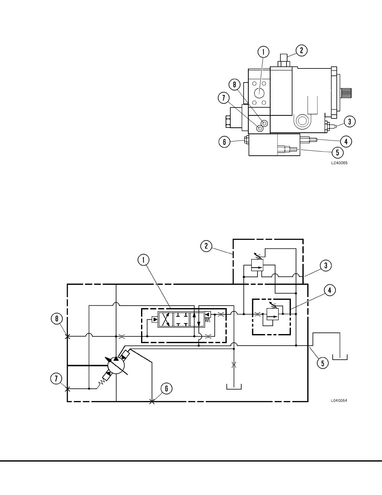
Figure 4-14 shows the steering pump and the location
of the pressure control adjustments and stroke (flow)
adjuster.
Note: The Stroke adjuster (3, Figure 4-14) is set at the
factory to provide maximum pump flow and adjust-
ment is not normally required. If the truck is operated
at high elevations, 10,000 ft. (3,050 meters) above sea
level or more, it may be necessary to readjust the
stroke control to reduce pump flow to prevent pump
cavitation under certain conditions. If the truck is oper-
ating at high altitude and problems are experienced,
consult the Komatsu Factory Representative for adjust-
ment procedures.
Figure 4-15 shows the schematic of the pump and the
pressure control valves.
FIGURE 4-14. STEERING PUMP ASSEMBLY
1. Outlet Port
2. Case Drain
3. Stroke Adjuster
4. Unloader Valve
Press. Adjust
5. Compensator Press.
Adjust
6. 4-Way Valve
7. GPA Port
8. GP2 Port
FIGURE 4-15. STEERING PUMP PRESSURE CONTROL SCHEMATIC
1. 4-Way Valve
2. Unloader Control Block
3. “ACC” Port
4. Pressure Compensator Control Block
5. Case Drain
6. GP2 Port
7. GP4 Port
8. GPA Port
L04031 Steering Circuit L4-19
 Loading...


