Cleaning and Inspection
1. Clean all parts including housings in solvent and
blow dry with compressed air.
2. Inspect seal counter bores, they must be free of
nicks or grooves.
3. Examine springs for breaks or distortion.
4. Inspect spool (14, Figure 8-14). The spool must
be free of longitudinal score marks, nicks or
grooves.
5. Test spool (14) in spool housing for fit. Spool must
fit freely and rotate through a complete revolution
without binding.
NOTE: The spool housing (17), spool (14), inlet hous-
ing (18) and outlet housing (7) are not serviced sepa-
rately. Should any of these parts require replacement,
the entire control valve must be replaced.
Assembly
1. Thoroughly coat all parts including housing bores
with clean type C-4 hydraulic oil.
2. If the inlet and outlet housings were removed
follow steps 3 through 5 for reassembly.
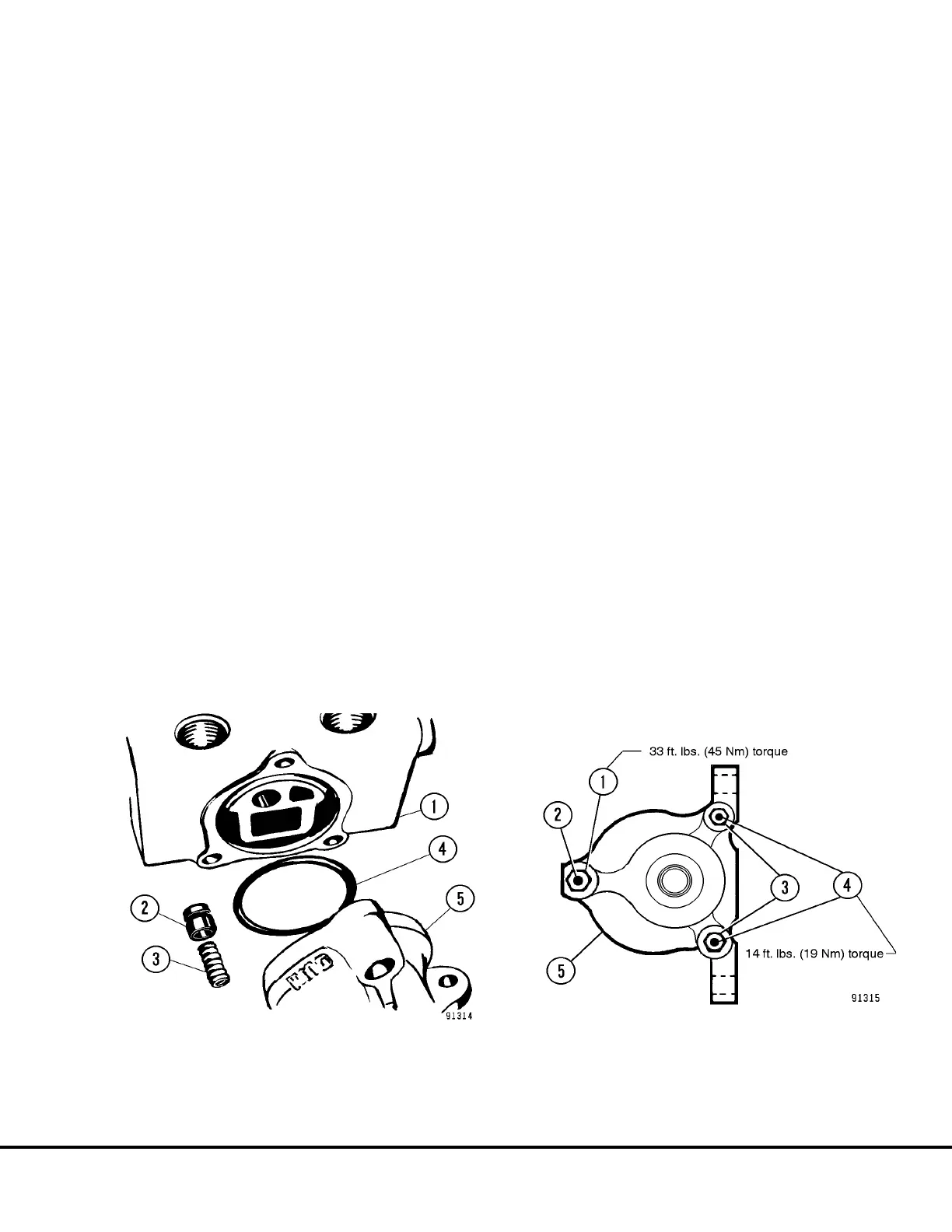
3. Install check poppet (2, Figure 8-16) and spring
(3) in spool housing (1).
4. Install new O-ring (4) in spool housing. Place the
inlet and outlet housings on the spool housing.
5. Install tie rods. Install tie rod nuts. Tighten tie rod
nuts to the torques shown in Figure 8-16.
6. Install a new O-ring (27, Figure 8-14) and wiper
(26). Install seal retainer (25).
7. Install spacer (5), spring seats (19), and spring
(4). Thread detent pin (3) into spool (14). Slight
pressure will be required to compress the detent
spring. Tighten detent pin to 84-96 in. lbs. (9-11
N.m) torque. Install spring (20). Carefully install
spool into spool housing.
8. Apply grease to the cross holes of the detent pin
(3) to hold balls (21) and (2).
9. Slide detent sleeve (22) into cap (24) and place
over a punch. Using this punch, depress ball (21)
and insert balls (2) in detent pin cross holes.
10. While holding down on ball (21), slide detent
sleeve (22) and cap (24) as an assembly over the
detent pin (3). Continue to insert detent sleeve
(22) until it contacts spring seat (19).
11. Secure cap (24) in place with capscrews (6).
Tighten capscrews (6) to 5 ft. lbs. (7 N.m) torque.
Install spacer (23) and snap ring (1).
12. Install a new O-ring (12) and wiper (13). Install
seal plate (16). Install machine screws (15).
13. Using new O-rings, install relief valve (2, Figure
8-15) in spool housing.
FIGURE 8-16. HOIST PILOT VALVE REASSEMBLY
1. Spool Housing
2. Check Poppet
3. Spring
4. O-ring
5. Outlet Housing
FIGURE 8-17. TIE ROD NUT TORQUE
1. Nut
2. Tie Rod
3. Nut
4. Tie Rod
5. Outlet Housing
L08024 Hoist Circuit Component Repair L8-11
 Loading...


