TEST 4 - Check For Grounded Field Coil
Set ohmmeter to x10K scale and make sure ohmmeter
is zeroed. Connect one ohmmeter lead to terminal “F-“
of the control unit harness. Connect the other ohmme-
ter lead to the front housing ground stud. The ohmme-
ter should read very high. If the ohmmeter reads less
than 100K ohms, the field coil is grounded and must
be replaced (replace or repair Stator & Shell Assem-
bly).
Move ohmmeter lead from “F-“ to “F+” (if so equipped),
or to “B+” and repeat test. The ohmmeter should read
very high. If the ohmmeter reads less than 100K ohms,
the field coil is grounded and must be replaced (re-
place or repair Stator & Shell Assembly).
CONTROL BOX TESTS
Note: Needle point probes may be required to pene-
trate the potting compound in the control box.
Refer to Figure 13-4 for location of control box terminal
strip connections. Refer to Figure 13-3 for location of
control box external connections to regulator and igni-
tion circuit.
TEST 5 -
Check Continuity Of Terminal Strip Connections
Set ohmmeter scale according to Table 13-6 and make
ohmmeter connections between the terminal strip in-
side the control box and control box terminals located
on the outside of the control box.
Table 13-6.
CONTROL BOX CONTINUITY CHECKS
OHMETER
SCALE
TERMINAL
STRIP
CONNECTION
(Figure 13-4)
CONTROL
BOX
EXTERNAL
CONNECTION
(Figure 13-5)
READING
x10K F- GND* (B-)
VERY
HIGH
x1 F- (F-) PIN ZERO
x1 F+
(F+)
TERMINAL
ZERO
*GND connections are made to ground terminal
located on outside of front housing.
With regulator disconnected, test for continuity from
“E” terminal on control unit to connector Energize (“E”)
pin on regulator harness (See Figure 13-5).
TEST 6 - Diode Heat Sink Tests
Check to make sure that all phase leads are discon-
nected from the heat sink (refer to Figure 13-6).
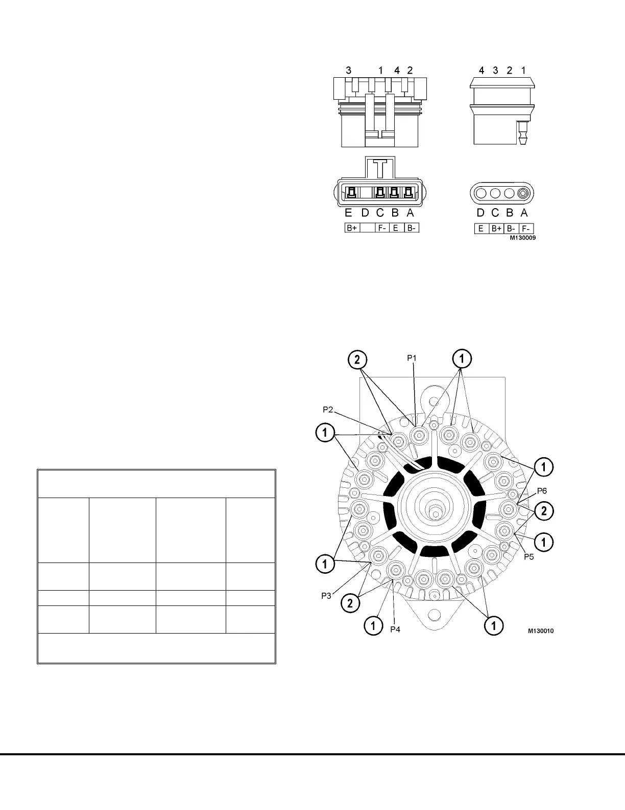
FIGURE 13-5.
Metri-Pack Connector SAE Connector
FIGURE 13-6.
1. Positive Diode Studs 2. "S" Phase Terminal
NOTE: Heat sink diodes are de-rated for heavy duty
performance. If diode failure is detected, the entire
charging system should be examined for loose con-
nections (especially battery). If diode failure is indi-
cated, stator failure must also be suspected.
M13-10 Niehoff Alternator Overhaul Manual M13003 04/01
 Loading...


