BATTERY CHARGING SYSTEM
(Niehoff)
General Description
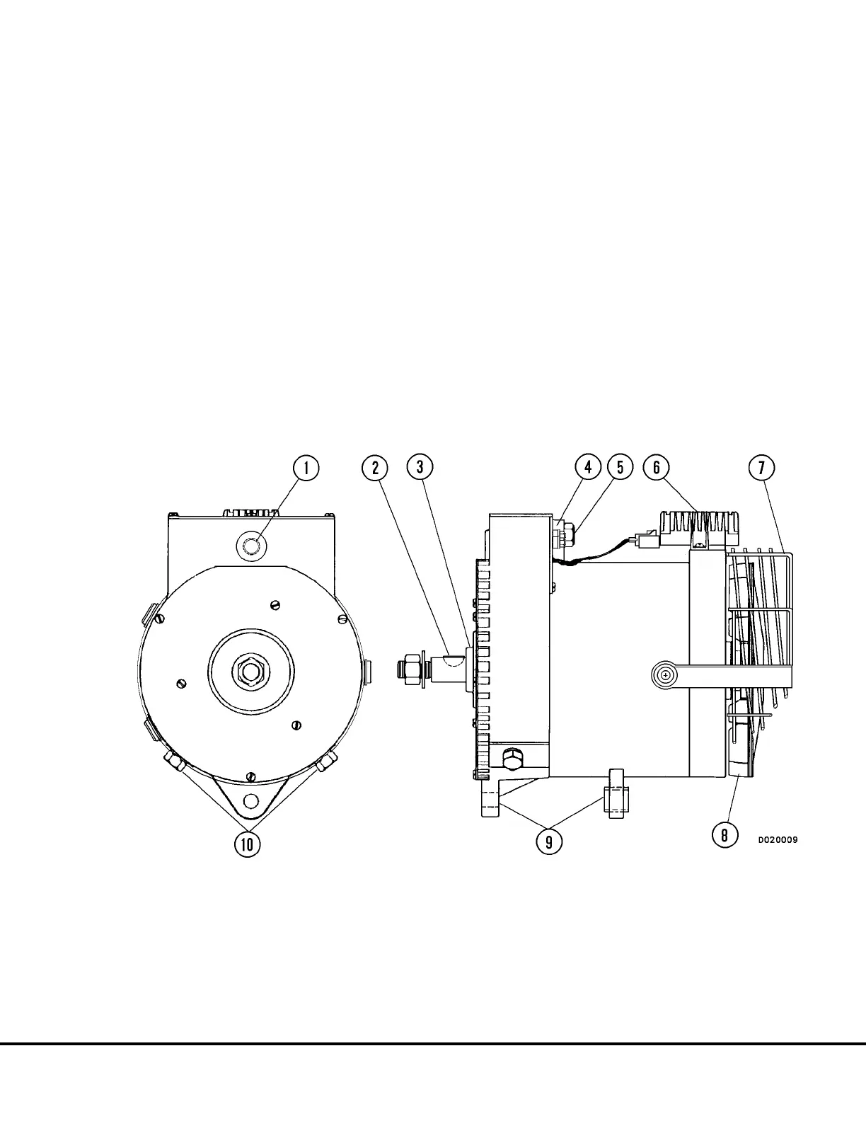
The Niehoff model N1227 or C609 (Figure 13-1) is a
heavy duty, 24 VDC unit rated at 220 amps. A solid
state voltage regulator (6) mounted externally on the
end housing assembly provides voltage control during
operation. A single output connection (5) is located on
the face of the control unit (4) for connection to the
truck battery positive circuit. The ground circuit cable
can be attached to either of two terminals (10) located
on the front housing. A fan guard (7) protects mainte-
nance personnel from the rotating fan when the engine
is operating.
TROUBLESHOOTING PROCEDURES
(On-Truck)
Most 24 volt charging system problems can be diag-
nosed with the alternator installed on the truck, oper-
ating under normal conditions. Many problems can be
attributed to loose or corroded cable connectors. It is
essential that all battery charging circuit cables are in
satisfactory condition and all connections are clean
and securely tightened.
Equipment Required:
• Belt tension scale
• Voltmeter, 0 - 40 volt range
• Ammeter, 0 - 400 amp range
FIGURE 13-1. ALTERNATOR ASSEMBLY
1. Belt tension Adjustment
Capscrew
2. Shaft Key
3. Pulley Bushing
4. Control Unit
5. Battery Positive Terminal
6. Voltage Regulator
7. Fan Guard
8. Cooling Fan Assembly
9. Mounting Lugs
10. Ground Terminals
M13002 2/99 24VDC Electric Supply System M13-3
with 220 Amp. Niehoff Alternator
 Loading...


