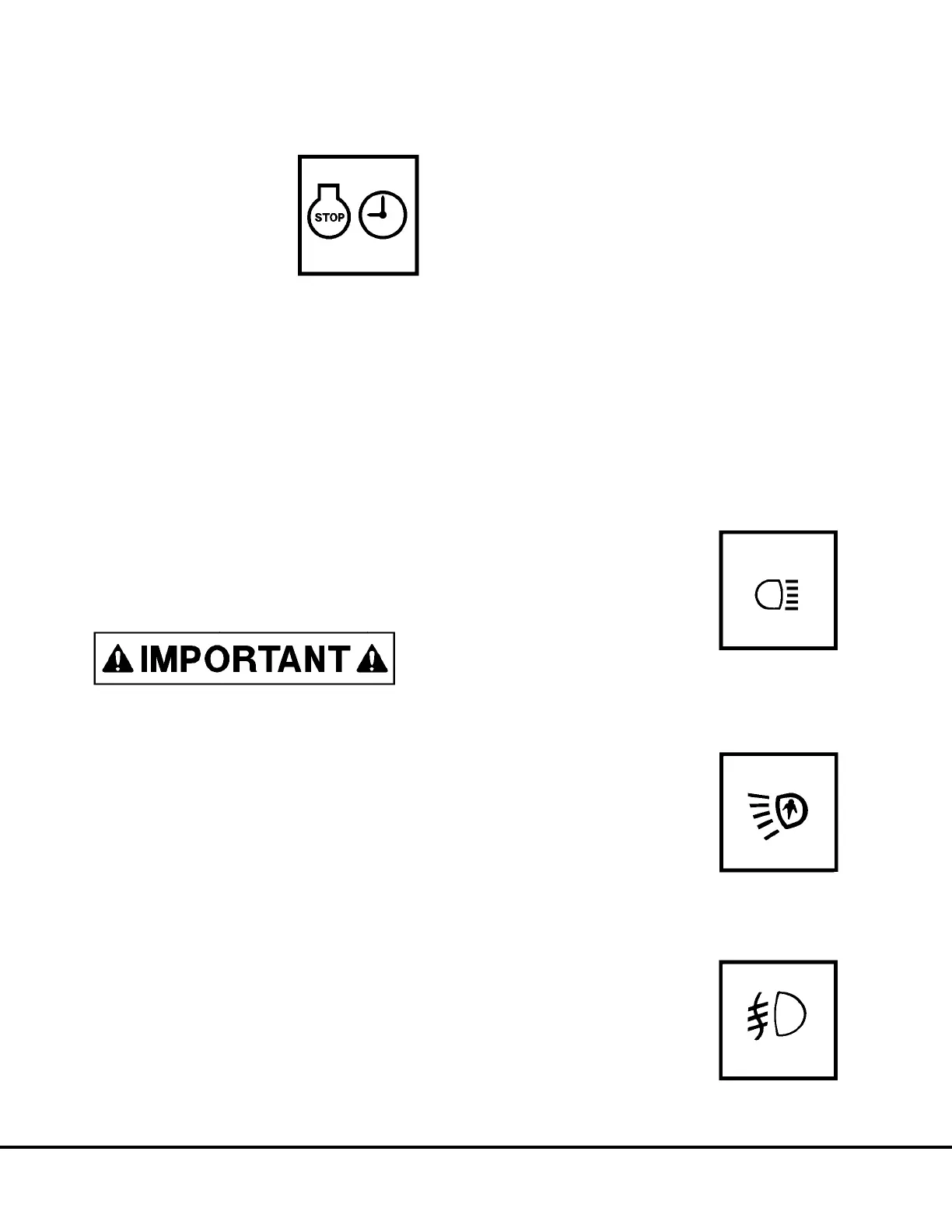
ENGINE SHUTDOWN SWITCH, with 5 Minute Idle
Timer delay
This switch (2, Figure 5-5) is a
3-position rocker-type switch
(Off-On-Momentary). The switch
activates a timer circuit that auto-
matically shuts down the engine
after a 5 minute cooling period at
low idle.
Operation
1. Stop truck. Reduce engine RPM to low idle. Place
Selector Switch in “Neutral” (see OPERATOR
CONTROLS) and apply Parking Brake switch.
Place REST switch in “On” position (put drive
system in “REST” mode of operation). Refer to
discussion of REST SWITCH (26, Figure 5-5).
a. Press top of switch to the “On” (center posi-
tion), then press firmly to the “Momentary”
(upper position) and hold briefly to activate the
5 Minute Idle Timer (switch is spring-loaded to
return to “On” position when released).
At the
same time, while holding the “Momentary”
switch position,
turn the keyswitch counter-
clockwise to the OFF position.
The engine WILL NOT SHUT DOWN if the
keyswitch is not turned OFF as described above.
NOTE: To cancel the 5 Minute Idle Timer sequence,
press Timer Delay Shutdown switch to the OFF (lower)
position.
•
••
• If the keyswitch is in the OFF position, the engine
will stop.
•
••
• If the keyswitch is in the ON position, the engine
will continue to run.
b. When the Engine Shutdown Timer has been
activated, the Timer Delay indicator light (C4,
Figure 5-6) in the overhead status panel will
illuminate to indicate that the shutdown timing
sequence has been started. The engine will
continue to run at Idle RPM for approximately
5 minutes to allow for proper engine cool-down
before stopping.
2. With keyswitch “Off”, and engine stopped, wait at
least 90 seconds. Insure steering circuit is com-
pletely bled down by turning steering wheel back
and forth several times. No front wheel movement
will occur when hydraulic pressure is relieved.
3. Verify all the LINK VOLTAGE lights turn off within
5 minutes after the engine is shut down. (One is
located in cab, behind the operator seat, two
others are located in the access panel at the left
front corner of the electrical cabinet.) If lights
remain on, refer to Section “E” for additional
instructions and information.
4. Close and lock all windows, remove key from
keyswitch and lock cab to prevent possible un-
authorized truck operation. Dismount truck prop-
erly.
MANUAL BACKUP SWITCH
The Manual Backup Switch (3,
Figure 5-5) allows backup lights to
be turned “On” providing added
visibility and safety when the Se-
lector Switch (see Operator Con-
trols) is not in “REV” position.
When the SWITCH is pressed to-
ward the “on” position, the MAN-
UAL BACK UP LIGHT indicator (B4, Overhead Panel,
Figure 5-6) will be illuminated.
LADDER LIGHT SWITCH
The switch (4, Figure 5-5) turns
the ladder lights “On” or “Off” after
or before using ladder. Pressing
the top of the rocker switch turns
the lights “On”. Pressing the bot-
tom of the switch turns the lights
“Off”. Another switch is mounted
at the front left of truck near the base of ladder.
FOG LIGHTS (OPTIONAL)
Fog Lights (5, Figure 5-5) are op-
tional equipment that are useful in
foggy conditions and heavy rain.
Pressing the top of the rocker
switch turns the lights “On”. Press-
ing the bottom of the switch turns
the lights “Off”.
N5-14 Operator Cab Controls N05044
 Loading...


