4. After rotating field coil bobbin, remove field coil
through back of stator and shell assembly (end
away from leads) while allowing field leads to
slide through opening in front stator assembly.
Notes: As field coil is removed from stator and shell
assembly note and mark position of leads relative to
drainage holes in shell for reassembly (Figure 13-19).
Loctite should be used on all screws and nuts as
machine is assembled, except where told otherwise.
For stator installation, see BF4822 Stator Service Tool
Instructions.
ALTERNATOR ASSEMBLY
FIELD COIL ASSEMBLY
1. Lay stator and shell assembly on its side, phase
leads to the left (Figure 13-20).
2. Insert field coil from right hand side of stator and
shell assembly, field leads (white wires with
spade terminals) facing toward phase leads.
3. As field coil is inserted into stator and shell assem-
bly thread the field leads through the proper open-
ings between the front stator windings.
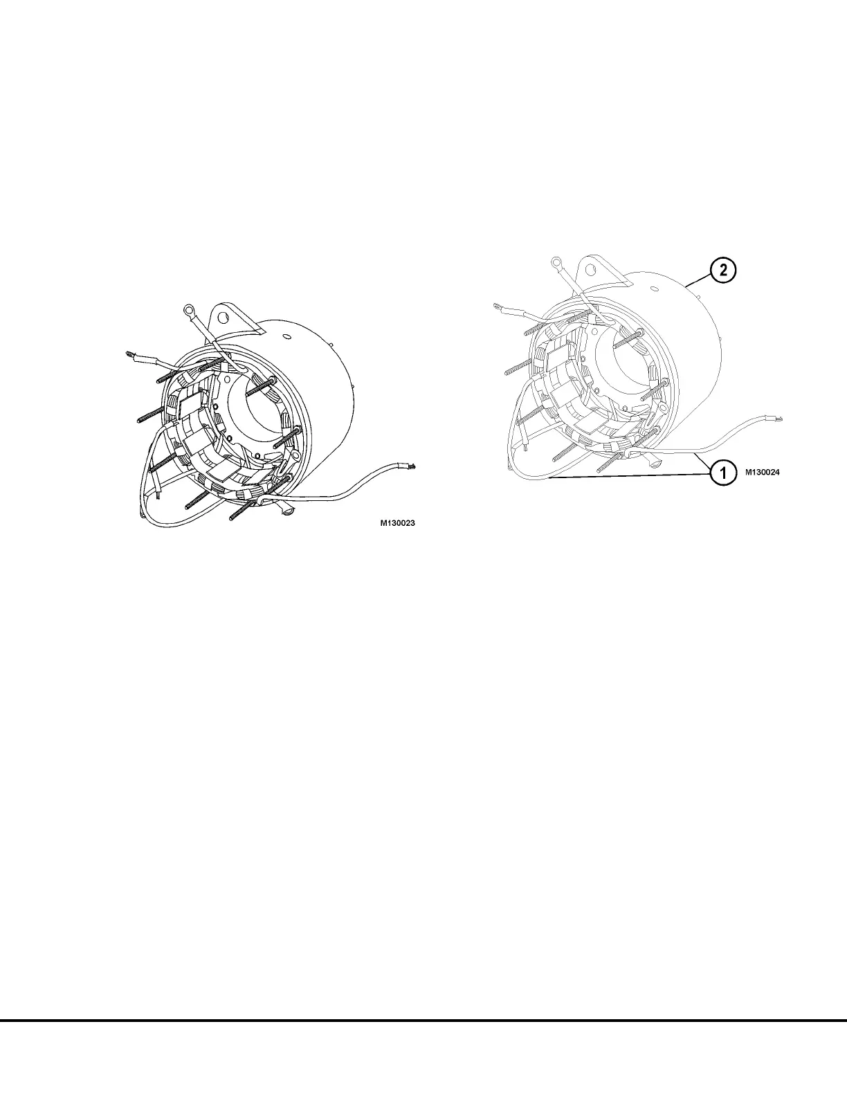
FIGURE 13-19.
FIGURE 13-20.
1. Field Leads 2. Remove or Insert
Field Coil from this end.
M13003 04/01 Niehoff Alternator Overhaul Manual M13-17
 Loading...


