FRONT WHEEL HUB AND SPINDLE
WHEEL HUB AND SPINDLE ASSEMBLY
The following instructions will cover the complete re-
moval, installation, disassembly, assembly and bear-
ing adjustment of front wheel hub and spindle. If only
brake service is to be performed, refer to Section “J”,
“Brake Circuit”.
Do not loosen or disconnect any hydraulic brake
line or component until engine is stopped, Key
switch is “Off” for 90 seconds and drain valves on
brake accumulators are opened.
PREPARATION
1. Reduce the engine speed to idle. Place the selec-
tor switch in NEUTRAL and apply the parking
brake. Be certain the parking brake applied indi-
cator lamp in the overhead panel is illuminated.
2. Place the drive system in the REST mode by
turning the Rest switch on the instrument panel
ON. Be certain the REST warning lamp is illumi-
nated.
3. Shut down the engine using the keyswitch. If, for
some reason the engine does not shut down, use
the shutdown switch on the center console.
4. Verify the LINK VOLTAGE lights are OFF. If they
remain on longer than 5 minutes after shutdown,
notify the electrical department.
5. Verify the steering accumulators have bled down
by attempting to steer.
6. Bleed down the brake accumulators using the
manual bleed valves on the brake manifold.
7. Open the battery disconnect switches.
Removal
Refer to the “Front Tire and Rim Removal” instructions
and remove front tire and rim assembly.
1. Close hydraulic pump shut-off valves.
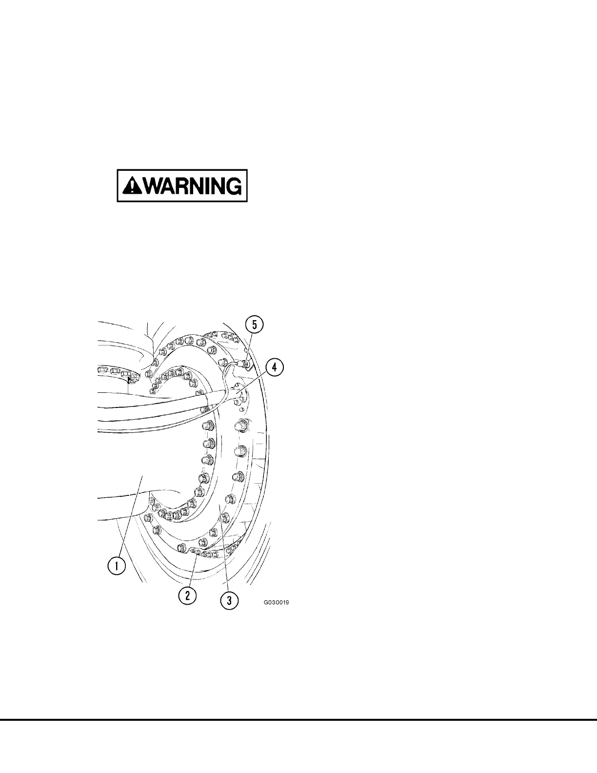
2. Disconnect speed sensor cable(s) (5, Figure 3-1)
at connector. Tie cables back away from spindle
to prevent damage during spindle removal.
NOTE: The left brake assembly has two speed sen-
sors installed.
3. Disconnect disc brake cooling oil hoses (4) at inlet
and outlet ports on brake housing. Also discon-
nect brake apply line. Cap hoses and ports to
prevent contamination. Remove the oil in the
brake housing and hub bearings by removing the
hex plug (2) and draining into a suitable container.
4. Remove lubrication lines from tie rod and steering
cylinder.
5. Disconnect tie rod and steering cylinder rod from
spindle being removed. Refer to “Steering Cylin-
der and Tie Rod Removal” in this section.
FIGURE 3-1. FRONT WHEEL & SPINDLE
INSTALLATION
1. Spindle
2. Brake Housing Drain
3. Disc Brake Housing
4. Brake Cooling Hose
5. Speed Sensor Connector
G03017 02/01 Front Wheel Hub and Spindle G3-1
 Loading...


