DISABLED TRUCK DUMPING
PROCEDURE
Sometimes it is necessary to dump a load from the
body of a truck when the hoist system is inoperable.
The following instructions describe the use of a “good”
truck to provide the hydraulic power required to raise
the body of the “disabled” truck to dump the load.
In the example below, Figure 8-25 illustrates a typical
hookup from the good truck. The disabled truck may
be another Model 930E-2, or a different Komatsu
model.
HOOKUP
Be certain there is an adequate, clear area to dump
the loaded box. When the good truck is in position, shut
down the engine and allow the hydraulic system to
bleed down. Be certain pressure has bled off before
connecting hoses.
1. With the good truck parked as close as possible
to the disabled truck, attach a hose from the
power up quick disconnect (4, Figure 8-25) to
the power down circuit of the disabled truck.
(Hose must be rated to withstand 2500 psi (17
MPa) or greater pressure.
NOTE: The power down circuit will use a smaller
diameter hose (tube) than the power up circuit.
2. Connect another hose from the power down
quick disconnect (3) to the power up circuit of
the disabled truck.
NOTE: If both trucks are a Model 930E-2, the hoses
will be installed at the quick disconnects shown in
Figure 8-25 and
will be crossed
when connected.
DUMPING PROCEDURE
Raising the Body:
3. On the disabled truck, move the hoist control
lever to power up and then release it to place the
hoist pilot valve in the HOLD position (leave in
this position during entire procedure).
4. Start the engine on the good truck, place the hoist
control in the power down position and increase
engine RPM to high idle to dump the disabled
truck. If the body of the disabled truck fails to
raise, increase the good truck power down relief
pressure as follows:
a. Shut down engine and allow the hydraulic
system to bleed down.
b. Remove the cap from the Hoist Pilot Valve relief
valve (2, Figure 8-15) located in the hydraulics
components cabinet behind the cab. While
counting the number of turns, slowly screw the
relief valve adjustment screw clockwise until it
bottoms.
5. Repeat step 4 to dump the disabled truck.
Lowering the Body:
6. Place the hoist lever of the good truck in FLOAT
to lower the body. If necessary, momentarily
place the hoist control in POWER UP until the
body is able to descend in FLOAT. Do not accel-
erate the engine.
7. After body is lowered, shut down the truck, bleed
the hydraulic system and disconnect the hoses.
8. Reduce power down relief valve pressure to
normal on good truck by turning the adjustment
counterclockwise the same number of turns as
required in step 4 b.
9. Check power down relief pressure per instruc-
tions in Section L10.
10. Check hydraulic tank oil level.
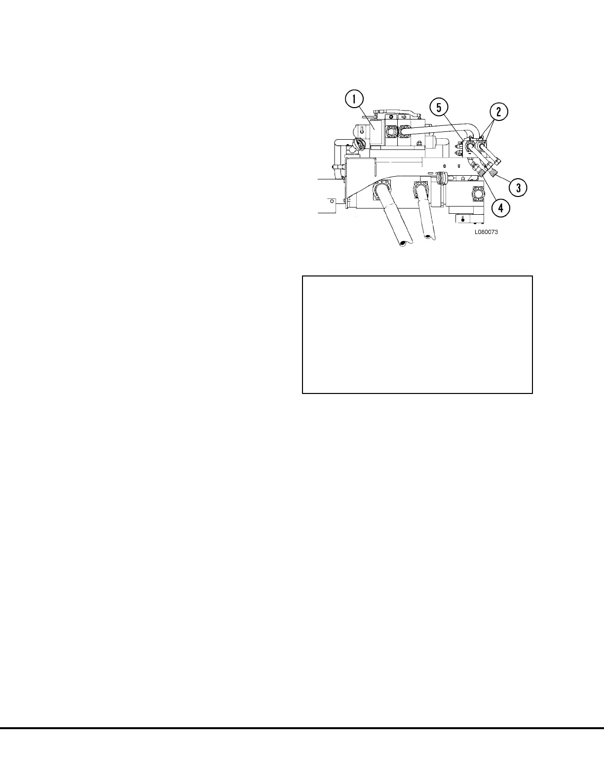
FIGURE 8-25. PUMP MODULE, HOSE HOOKUP
(Model 930E-2 shown)
1. Hoist Valve
2. Tubes to LH Hoist Cylinder
3. Power Down Quick Disconnect; Connect
to power up circuit of “disabled” truck
4. Power Up Quick Disconnect; Connect to
power down circuit of “disabled” truck
L8-20 Hoist Circuit Component Repair L08024
 Loading...


