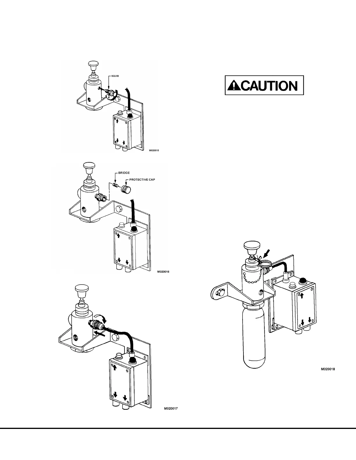
Installation Procedure for Squib
After all testing has been completed and all test kit
components removed, proceed to arm the system.
Using wrench, insert squib into upper right inlet hole
on actuator body and firmly tighten (Figure 2.3-15).
After installing squib into actuator body, loosen protec-
tive shipping cap from squib and remove bridge
(Figure 2.3-16).
Always install squib into actuator body first, before
installing connector onto threaded body of squib.
Possible injury could result if squib was actuated
outside of actuator body.
Install squib connector onto threaded stud of squib
(Figure 2.3-17). Handtighten as firmly as possible.
Placing the Electric Detection & Actuation System
Into Service
To place the Electric Detection and Actuation System
into service, proceed as follows:
1. Check all fasteners for tightness. Insure jam nut on
actuator body is securely tightened.
2. Before installing actuator cartridge, push manual
puncture lever several times to insure smooth
operation.
3. Insert ring pin in hole and attach lead wire seal (See
Figure 2.3-18).
4. Insert LT-5-R cartridge (PB0674) into lower actua-
tor body and handtighten firmly.
5. Record date that system was placed in service.
FIGURE 2.3-15.
FIGURE 2.3-16.
FIGURE 2.3-17. INSTALL SQUIB
FIGURE 2.3-18. INSTALL ACTUATOR CARTRIDGE
M02003 Ansul "Checkfire" Electric Detection and Actuation System M2.3-5
 Loading...


