ACCUMULATORS - FRAME MOUNTED
Figure 3-26 illustrates the (RH) frame mounted brake
circuit accumulators which provide additional oil stor-
age for the front and rear brake circuits.
Removal
1. Place the selector switch in NEUTRAL, turn the
rest switch ON. Turn key switch OFF to shut down
engine and allow at least 90 seconds to allow
steering accumulator oil to drain back to tank.
2. Open Needle valves (6 & 7, Figure 3-1) on brake
manifold (5) and allow the four brake system
accumulators to bleed completely.
3. Remove charging valve guard (2, Figure 3-25)
and loosen small hex on charging valve (3) three
complete turns. Depress the valve core until all
nitrogen pressure has been relieved.
Make certain only the small swivel hex nut turns.
Turning the complete charging valve assembly
may result in the valve assembly being forced out
of the accumulator by the nitrogen pressure in-
side. Wear protective face mask when discharging
nitrogen gas.
4. Remove oil line (5, Figure 3-26) from bottom of
the accumulator. Plug all hoses and openings to
prevent possible contamination of the system.
5. Attach a lifting device to the accumulator to be
removed.
6. Remove the mounting band capscrews, washers,
and nuts (3)and remove the mounting bands (4).
7. Raise the accumulator until clear of mounting
bracket and move to a clean work area for disas-
sembly.
Installation
1. Lift accumulator into position on the mounting
bracket. Accumulator should be positioned with
the antirotation block positioned between the two
stop blocks on the lower mounting bracket.
2. Secure the accumulator to the mounting bracket
using mounting bands (4, Figure 3-26), cap-
screws, lockwashers and nuts. Do not overtighten
nuts, as this could distort the accumulator.
3. Reconnect oil line to the bottom of the accumula-
tor.
4. Precharge both accumulators with pure dry nitro-
gen as outlined in “Frame Mounted Brake Accu-
mulator Charging Procedure”.
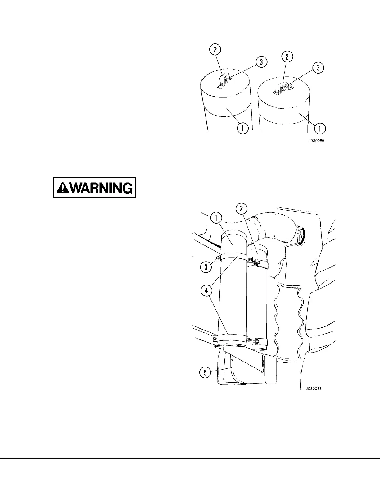
FIGURE 3-25. CHARGING VALVES
1. Accumulator
2. Charging Valve
Guard
3. Charging Valve
FIGURE 3-26. BRAKE ACCUMULATOR
INSTALLATION
1. Rear Brake Circuit
Accumulator
2. Front Brake Circuit
Accumulator
3. Capscrews, Washers
& Nuts
4. Mounting Bands
5. Oil Line
J3-26 Brake Circuit Component Service J03019 1/99
 Loading...


