PSC Digital Input Checks:
The following tests are made on the “Manual Test
Screen” as selected during PSC Digital Output Test
procedure.
1. With the key switch and the Control Power Switch
ON:
Verify the digital inputs in steps 1 through 5
in Table V below are highlighted.
2. Check digital inputs in Table steps 7 through 9
using the instructions in the Device Checkout
column.
¤
Highlight CPRL on the digital output section of
the PTU screen and then press {enter}.
3. Turn OFF the key switch in the cab.
KEYSW and CPSFB will no longer be high-
lighted
4. Turn ON the key switch.
5. Turn OFF the Control Power Switch.
KEYSW will stay highlighted, CPSFB will no
longer be highlighted.
6. Turn ON the Control Power Switch.
¤
Press {enter} to turn off CPRL.
¤
{escape} {escape}
7. Turn OFF Control Power Switch.
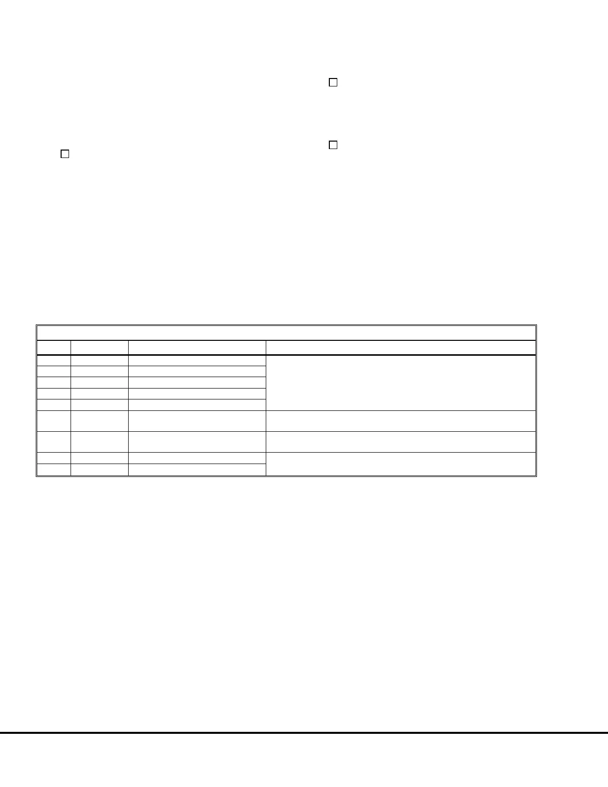
TABLE V: PSC DIGITAL INPUT TEST
STEP DI NAME DESCRIPTION DEVICE CHECKOUT
1 KEYSW Key Switch
With the Key Switch and Control Power Switch ON, digital inputs should
be highlighted.
2 CPSFB Control Power Switch Feedback
3 CNFB Panel Connectors Status
4 CNIFB CNI and CNENG Connector Status
5 CNXFB Auxiliary Blower Connector Status
6 INV1CO Inverter 1 Cutout Switch Status
Will be highlighted with Inverter #1 switch on the side of the control
cabinet in the CUTOUT position (down).
7 INV2CO Inverter 2 Cutout Switch Status
Will be highlighted with Inverter #2 switch on the side of the control
cabinet in the CUTOUT position (down).
8 BRKON1 Service Brake Apply Status Will be highlighted with wire 44R (TB26) jumpered to 712 (TB22) (Wires
do not have to be removed.)
9 BRKON2 Service Brake Apply Status
E3-20 AC Drive System Electrical Checkout Procedure 3/01 E03015
(Release 17 Software)
 Loading...


