Power Up Relief Pressure Test
The hoist valve contains two relief valves. The rear
inlet section (toward rear of truck) contains the relief
valve for the rear section of the hoist pump. The front
inlet section (toward front of truck) contains the relief
valve for the front section of the hoist pump.
1. To allow full extension of the hoist cylinders,
disconnect the hoist up limit solenoid, located on
the bottom of the bleeddown manifold from the
wiring harness.
Be sure there is adequate (safe) overhead clear-
ance before raising body to full up position.
2. With engine at low-idle, place hoist lever in
POWER UP position and hold until body is in the
full raised position. (Be certain gauges are iden-
tified as to the front or rear section of the pump
when pressures are read.)
Pressure at both hoist pump filter test ports
should be 2500 ±100 psi (17,237 ±690 kPa).
* Record on Data Sheet
Adjustment
If hoist relief pressure is incorrect on either gauge, the
corresponding relief valve should be readjusted. Ad-
just relief valve in rear hoist valve inlet section if the
rear pump section pressure was incorrect and/or ad-
just the relief valve in front hoist valve inlet section if
the front pump section pressure was incorrect.
1. If power up relief pressure is incorrect in either
the front or rear inlet section, adjust pressure as
follows:
a. Lower body until it is resting on frame rails and
shut down engine. Wait at least 90 seconds
until accumulators bleed down.
b. Relieve all hydraulic pressure from hoist sys-
tem.
c. Move hoist control lever to the “power down”
position and allow body to completely rest on
frame rails.
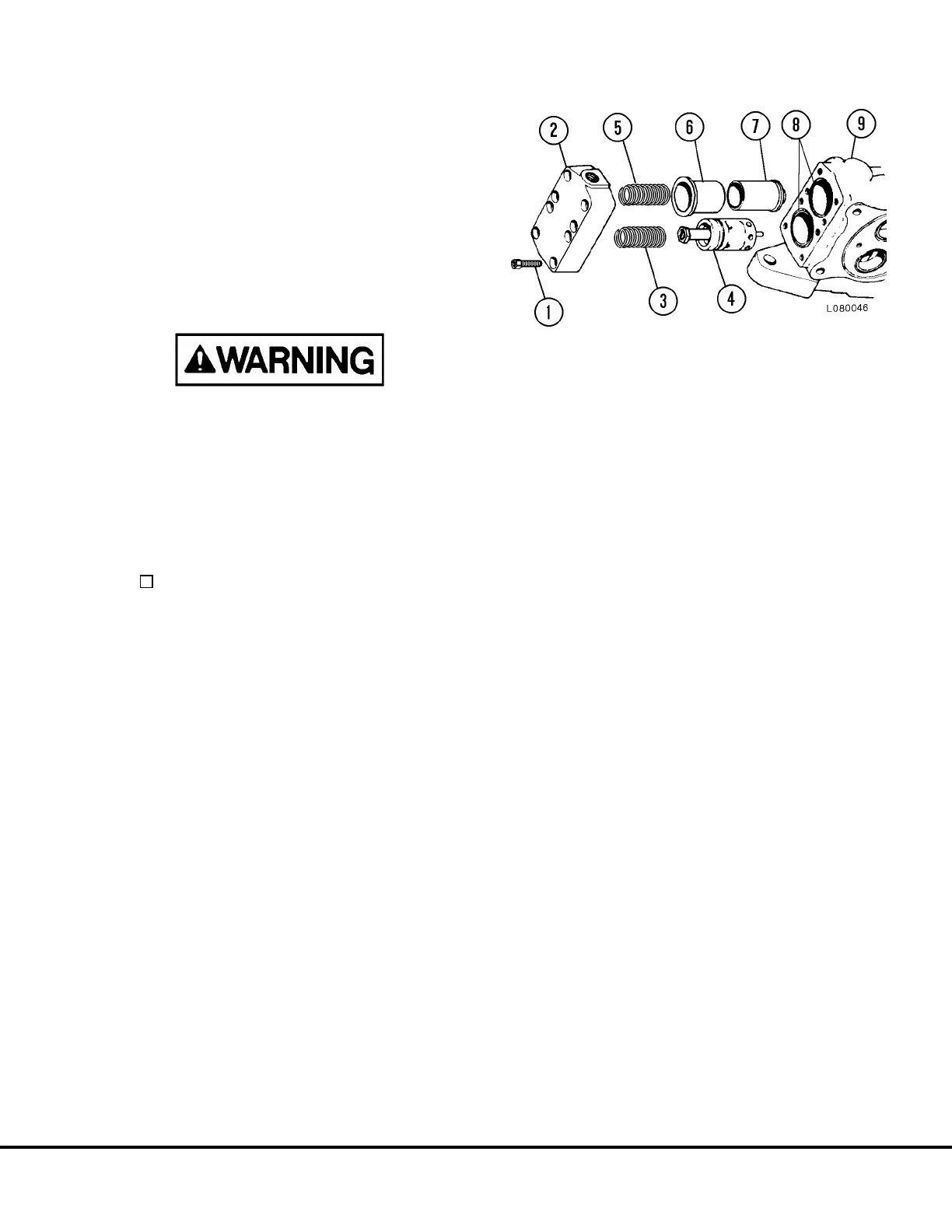
d. Disconnect tube from inlet section cover (2,
Figure 10-5). Disconnect hose(s) at top port.
e. Remove capscrews (1) from cover (2). Re-
move cover (1) and spring (3) from relief valve
(4).
f. Loosen jam nut on relief valve (4) and turn
screw “in” (clockwise) to increase pressure or
“out” (counter-clockwise) to decrease pres-
sure.
NOTE: Each 1/4 turn of the adjustment screw
will cause approximately 150 psi (1,034 kPa)
change in pressure.
g. Install spring (3) and cover (2) with new O-rings
(8). Install and tighten capscrews (1). Install
tube to cover fitting. Install hose(s) at top port.
2. Check pressure again, repeating step 2. If nec-
essary, repeat adjustment procedure until cor-
rect pressure is attained.
FIGURE 10-5. INLET SECTION
(Front and Rear Inlet Sections are Identical)
1. Capscrew
2. Inlet Cover
3. Spring
4. Main Relief Valve
5. Spring
6. Sleeve
7. Secondary Low
Pressure Valve
8. O-Rings
9. Inlet Valve body
L10012 Hydraulic Check-out Procedure L10-7
 Loading...


