Disassembly
1. Remove counterpressure valve plug (17, Figure
6-7), and O-ring (16). Remove counterpressure
valve assembly (15).
2. Remove plug (18) and seal (19). Using an 8 mm
hex allen head wrench, remove the relief valve
assembly (54). Remove steel seal (55).
3. Remove capscrew (35) and capscrews (34) using
a 10 mm and 13 mm hex head allen wrench.
Remove lockwashers (36 & 37). Remove end
cover (39).
4. Remove spring stop (42) and spring (43). Remove
spring stop (32) and springs (30 & 31). Remove
O-rings (38 & 40).
5. Remove spring control (29) and main spool (27).
Remove priority valve spool (44). Remove spring
control (23), springs (21 & 22) and spring stop
(20).
6. Remove amplifier valve spool assembly (53). Set
amplifier valve spool assembly aside for further
disassembly, if required.
7. Remove shock and suction valve (26). Set shock
and suction valve aside for further disassembly, if
required.
8. Remove capscrews (1 & 3) using a 10 mm and 13
mm hex head allen wrench. Remove lockwashers
(2 & 4). Remove end cover (5).
9. Remove O-rings (6, 7 & 8). Remove spring (52).
10. Remove shock and suction valve assembly (12).
Set the shock and suction valve aside for further
disassembly, if required. Remove orifice screw
(13).
11. Remove orifice screw (45). Remove check valve
(47).
NOTE: If further disassembly is required for the shock
and suction valves refer to Figure 6-8.
NOTE: The flow amplifier valve is equipped with two,
identical shock and suction valves. The shock and
suction valves are only serviced as complete valve
assemblies. O-rings 1 & 3, Figure 6-8 are replaceable.
The check valve (47) and counterpressure valve (15)
are also serviced only as assemblies.
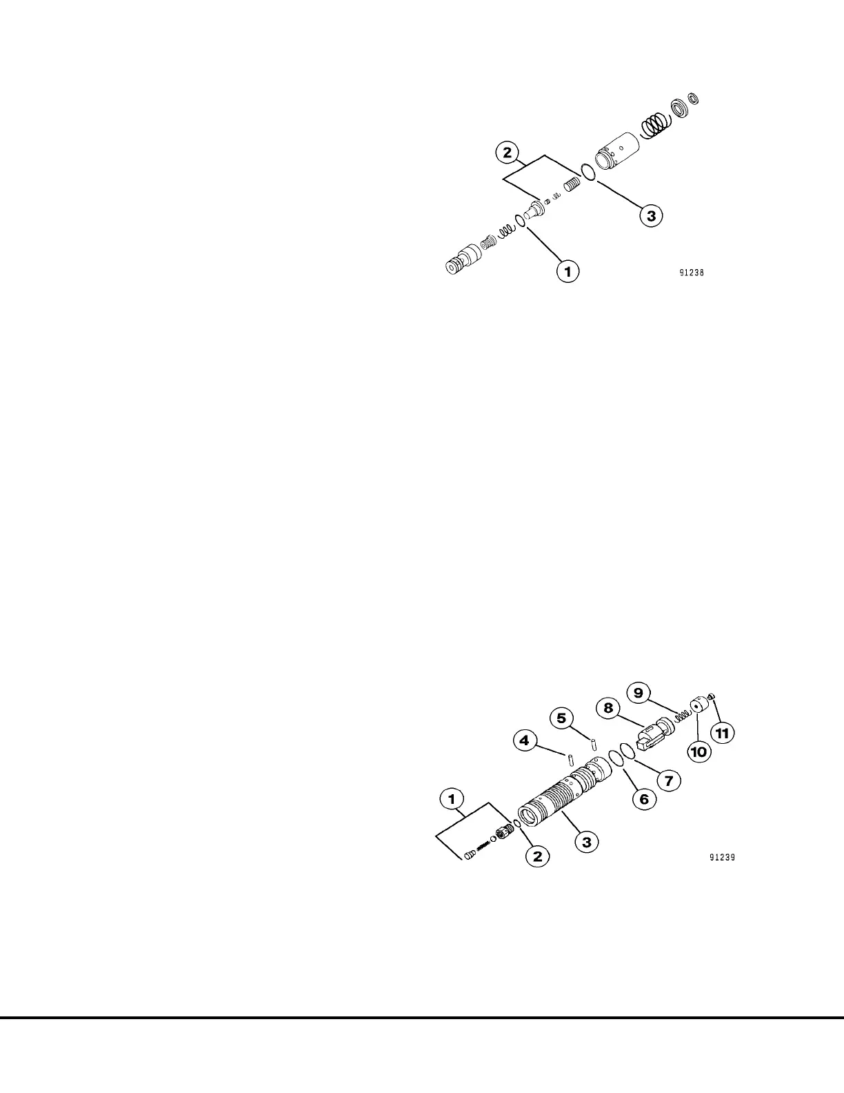
NOTE: Disassembly of the amplifier spool assembly is
only necessary should O-ring (2, Figure 6-9), spring
(9) or orifice plug (11) require replacement. Otherwise,
replace the amplifier spool assembly as a complete
unit. For complete disassembly refer to steps 12 & 13.
12. Remove retaining ring (7, Figure 6-9), remove pin
(5). Remove plug (10) and spring (9). Remove
retaining ring (6) and pin (4) and remove inner
spool (8).
13. Unthread check valve (1) and remove. Remove
O-ring (2). Remove orifice screw (11) from plug
(10).
14. Clean and inspect all parts carefully. Make any
replacements necessary.
FIGURE 6-8. SHOCK AND & SUCTION VALVE
ASSEMBLY
1. O-Ring
2. Pilot Section
3. O-Ring
FIGURE 6-9. AMPLIFIER SPOOL ASSEMBLY
1. Check Valve
2. O-Ring
3. Spool
4. Pin
5. Pin
6. Retaining Ring
7. Retaining Ring
8. Inner Spool
9. Spring
10. Plug
11. Orifice Plug
L6-8 Steering Circuit Component Repair L06021