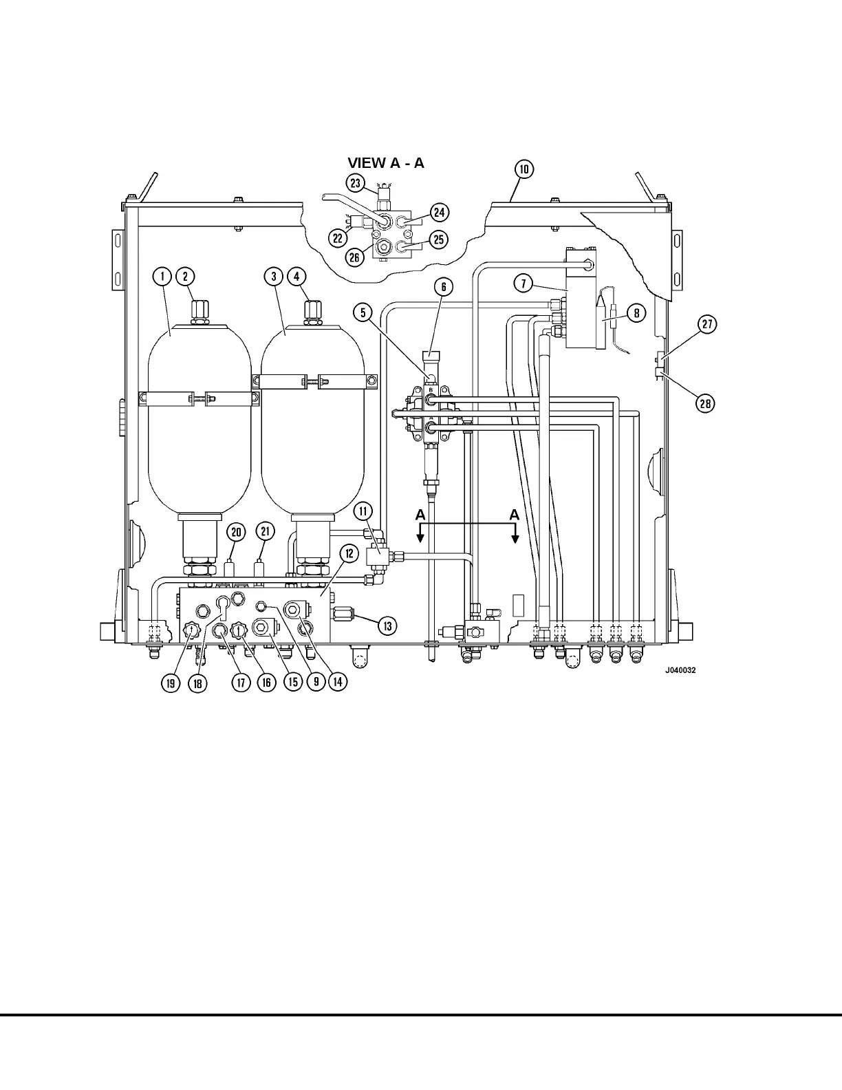
FIGURE 2-1. HYDRAULIC COMPONENTS CABINET
1. Rear Brake Accumulator
2. Charging Valve
3. Front Brake Accumulator
4. Charging Valve
5. Relief Valve (Hoist-Power Down)
6. Hoist Pilot Valve
7. Dual Relay Valve
8. Differential Pressure Sw.
9. Park Brake Release Press (PK2)
10. Brake Cabinet
11. Brake Lock Shuttle Valve
12. Brake Manifold
13. Pressure Reducing Valve (PR)
14. Brake Lock Solenoid (SV1)
15. Park Brake Solenoid (SV2)
16. Front Brake Accum. Bleed Valve
17. Automatic Apply Valve
18. Low Accum. Test Port (LAP1)
19. Rear Brake Accum. Bleed Valve
20. Low Brake Pressure Switch
21. Park Brake Pressure Switch
22. Stop Light Pressure Switch
23. Brake Lock Degradation Switch
24. Rear Brake Pressure Test Port (BR)
25. Front Brake Pressure Test Port (BF)
26. Manifold
27. Brake Warning Delay Timer
28. Brake Warning Relay
J2-2 Brake Circuit J02027
 Loading...


