HYDRAULIC SYSTEM
The following is a general description of the Model
930E hydraulic system. Additional information con-
cerning individual component description and opera-
tion can be found under the different system circuits
such as the hoist circuit, steering circuit, and hydraulic
brake circuit.
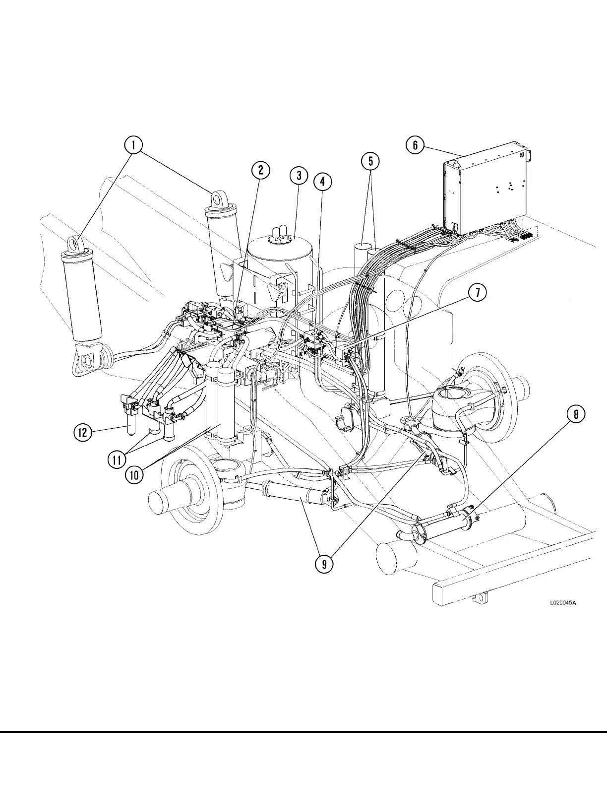
FIGURE 2-1. HYDRAULIC SYSTEM COMPONENTS AND PIPING
1. Hoist Cylinders
2. Hoist Valve
3. Hydraulic Tank
4. Bleeddown Manifold
5. Steering Accumulators
6. Hydraulic Components Cabinet
7. Flow Amplifier Valve
8. Heat Exchanger (Brake System Cooling)
9. Steering Cylinders
10. Brake System Auxiliary Accumulators
11. Hoist Circuit Filters
12. Steering Circuit Filter
L02028 Hydraulic System L2-1
 Loading...


