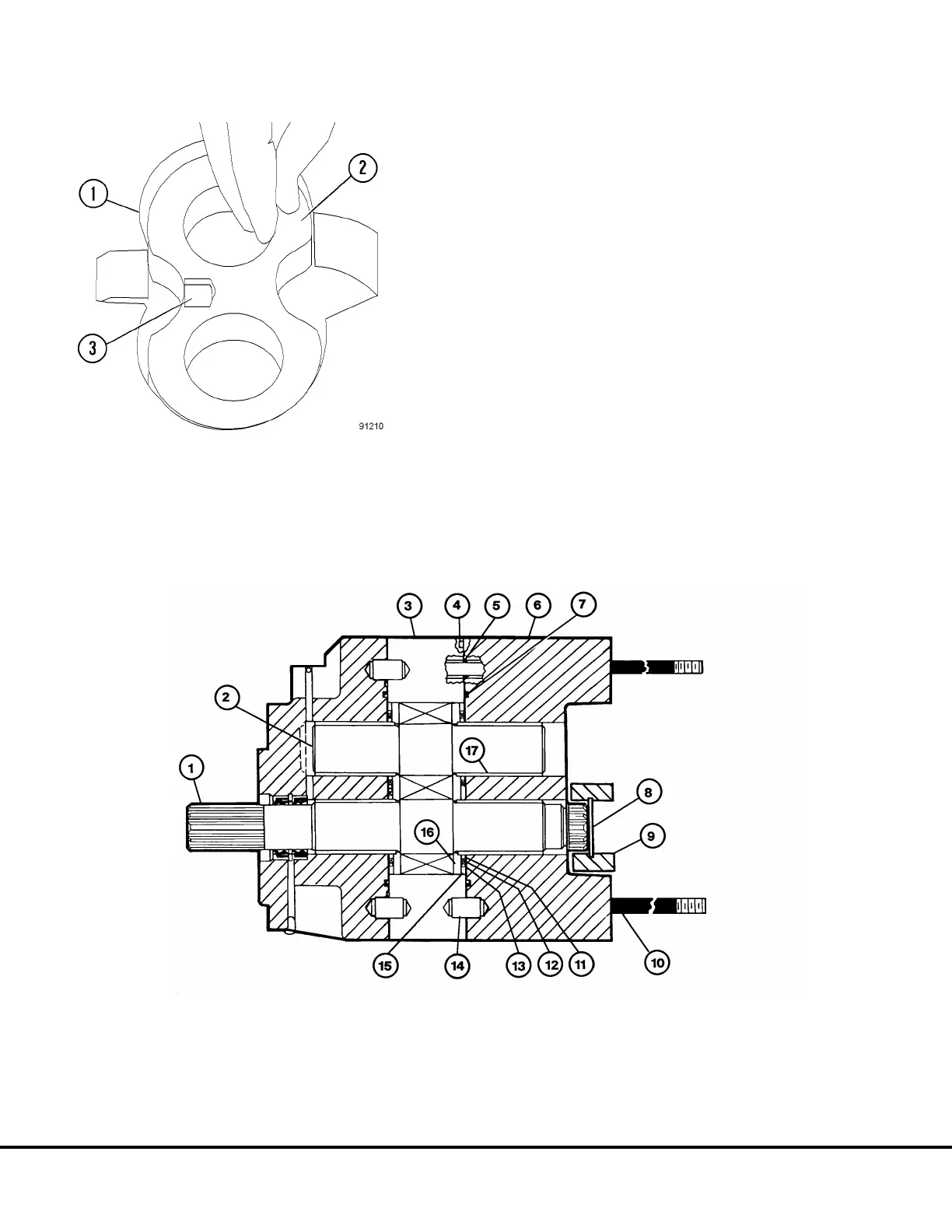
15. Install the opposite pressure plate with the bronze
side down and the milled slot facing toward the
discharge side.
16. Install steel rings (11, Figure 3-14), backup ring
(12), O-ring and retainer (13). Install isolation plate
with its relief toward the pressure plate.
17. Lubricate and install thru stud O-rings (5) and
connector plate O-ring (7). Install dowel (14) if
removed. Lubricate the I.D. of the bearings (17)
and install connector plate (6). Install snap ring (8)
and coupling (9).
FIGURE 3-13. PRESSURE PLATE INSTALLATION
1. Gear Plate
2. Pressure Plate
3. Slot
FIGURE 3-14. HOIST PUMP REASSEMBLY
1. Drive Gear & Shaft
2. Idler Gear
3. Gear Plate
4. Relief
5. O-ring
10. Thru Studs
11. Steel Ring
12. Backup Ring
13. O-ring & Retainer
14. Dowel
15. Isolation Plate
16. Pressure Plate
17. Bearings
6. Connector Plate
7. O-ring
8. Snap Ring
9. Coupling
L3-10 Hydraulic Component Repair L03027