3. Depress the charging valve core to release nitro-
gen pressure from the suspension. When nitro-
gen pressure has been vented to atmosphere,
loosen and remove the charging valve. The sus-
pension should have collapsed slowly as gas
pressure was released. Truck weight is now sup-
ported by the support blocks.
4. Use a plastic tube to help bleed off trapped air
inside the piston. Remove vent plugs and the
bleeder screw. Service the suspension with clean
HYDRAIR
®
Oil until clean oil comes out of the port
where the bleeder screw and plug were removed
from the side of the housing. Drip pans should be
used and all spillage cleaned from outside of
suspension. Allow suspension to stand for at least
15 minutes to clear any trapped nitrogen and/or
air bubbles from the oil. Add oil if necessary.
Loosely install charging valve.
Rear Suspension Nitrogen Charging
Lifting equipment (overhead or mobile cranes, or
hydraulic jacks) must be of sufficient capacity to
lift the truck weight. Be certain that all personnel
are clear of lift area before lift is started.
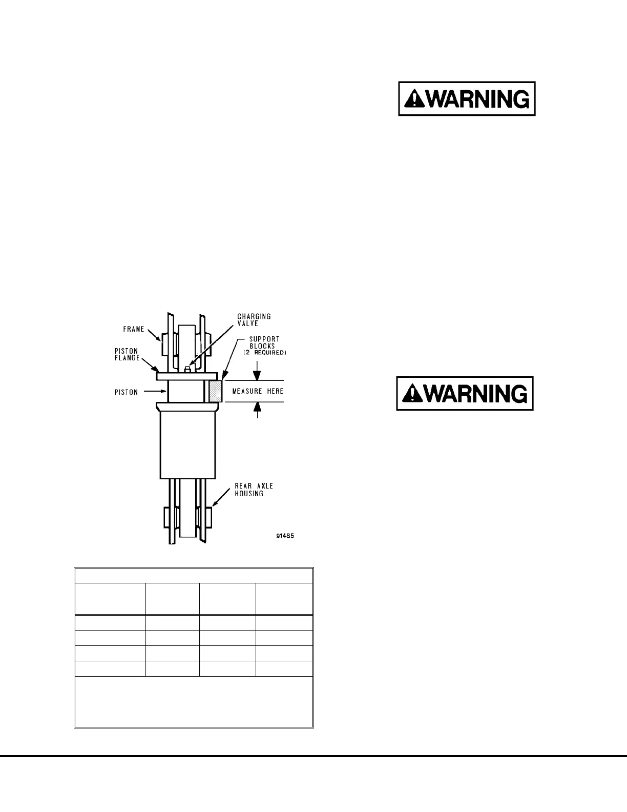
1. With nitrogen charging support blocks at hand
(see Figure 4-4), proceed as follows:
a. With overhead crane or jacks raise the truck
frame to provide clearance for blocks.
b. Install nitrogen charging dimension blocks; se-
cure blocks so they will not fly free.
c. Lower truck frame until the blocks are firmly and
squarely seated between the piston flange and
cylinder housing.
NOTE: Prevent damage to plated surface, oil seals
and capscrew heads.
Dry nitrogen is the only gas approved for use in
HYDRAIR
®
II suspensions and accumulators.
Charging of these components with oxygen or
other gases may result in an explosion which
could cause fatalities, serious injuries and/or ma-
jor property damage.
Use only nitrogen gas meeting the specifications
on the “Nitrogen Specifications Chart”.
2. Install charging valve, with a new lubricated seal-
ing O-ring (9, Figure 4-2) (use fresh HYDRAIR
®
oil). Tighten valve body (large hex) (6) to 16.5 ft.
lbs. (22.4 N.m) torque. The valve swivel nut (4)
(small hex) must be unseated (counterclockwise)
about three full turns.
3. Install HYDRAIR
®
Charging Kit and bottle of pure
dry nitrogen. Following previous instructions,
charge the suspensions with nitrogen gas to the
pressure shown in Figure 4-4 for the truck being
serviced. DO NOT use an overcharge of nitrogen
gas to lift the suspension off the blocks.
4. Shut off gas pressure and remove charging kit
components.
FIGURE 4-4. REAR SUSPENSION
REAR SUSPENSION DIMENSIONS (EMPTY)
TRUCK
MODEL
& OPTIONS
OILING
HEIGHT
in. (mm)
CHARGING
HEIGHT
in. (mm)
CHARGING
PRESSURE
psi (kPa)
730E* 1.0 (25.4) 9.0 (229) 280 (1931)
830E* 1.0 (25.4) 9.5 (241) 250 (1724)
830E** 1.0 (25.4) 9.5 (241) 315 (2172)
930E*, E-2* 1.0 (25.4) 7.5 (190) 215 (1482)
* with Standard Rock Body
** with Combination Body /Tailgate
Note: If truck starts to lift off blocks before charging
pressure is attained, STOP CHARGING.
H04005 9/99 Oiling and Charging Procedures H4-5
730E, 830E, and 930E
 Loading...


