3. Install the orange back-up ring (4) on top of the
poly-pak seal. Start by hand and then continue to
work into the groove either by hand or by using
an O-ring installation tool.
4. Install the wiper seal (5) in the top counterbore.
Position the seal in the groove so that the register
lip is facing up toward the actuator.
5. Repeat Steps 1- 4 for the second bore.
Regulator Sleeve O-Ring Installation
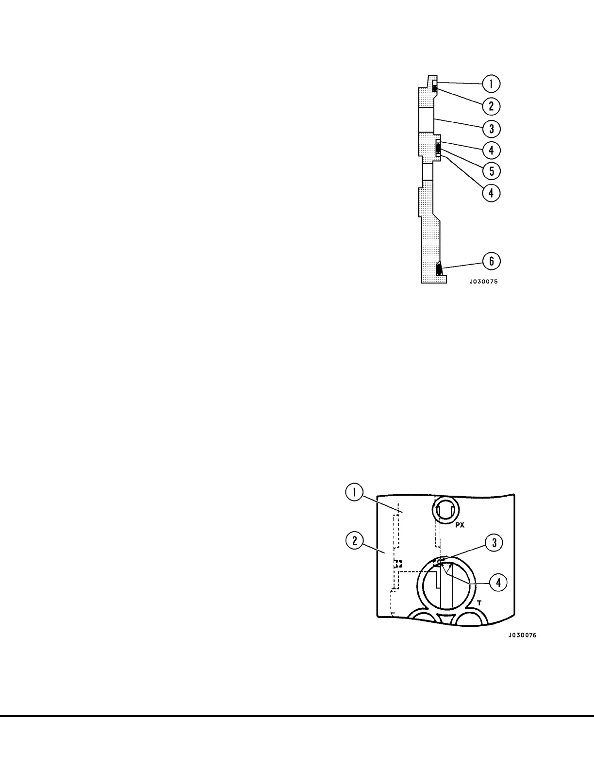
1. Install an O-ring (2, Figure 3-6) onto the smallest
groove (on the top) of the regulator sleeve (3).
Install O-ring (5) onto the middle groove on the
regulator sleeve. Install O-ring (6) onto the largest
groove (on the bottom) on the regulator sleeve.
2. Install a split nylon back-up ring (4) onto each side
of the O-ring (5) located in the middle of the
regulator sleeve.
3. Install one split nylon back-up ring behind the
O-ring (2) located at the top end of the sleeve.
This O-ring is the smallest of the three O-rings.
Position the back-up ring so that it is next to the
top of the regulator sleeve. The top of the sleeve
is the end with the smallest O.D.
4. Repeat Steps 1-3 for the second regulator sleeve.
Actuator Plunger O-ring Installation
1. Install an O-ring (7, Figure 3-4) into the O-ring
groove located at the large diameter end of the
actuation plunger (3).
2. Install a split Glyde ring over the O-ring. (Twist and
squeeze the split Glyde ring into a small circle
before installing to insure a tight fit over the O-
ring).
3. Repeat Steps 1 & 2 for the second plunger.
Assembly of Valve
NOTE: Start with either side (circuit) of the valve and
build that side complete through Step 4. before starting
on the other side (circuit). Be careful to assemble
components into the circuit from which they were
removed.
1. If removed, install stud (4, Figure 3-4) in plunger
(3). Tighten nut (2).
2. Install new packing (5) on staging seat (6) and
insert in plunger bore.
3. Lightly lubricate the actuation plunger Glyde ring
(7).
4. Install the “B1” actuation plunger (3) into the “B1”
circuit. Be careful not to damage or cut the Glyde
ring during installation. Observe the Glyde ring
assembly through the tank port as the plunger is
being installed. (Refer to Figure 3-7) It may be
necessary to work the Glyde rings past the sharp
edge in the body to prevent damage to the seal.
Make sure the actuation plunger is completely
seated and bottomed.
FIGURE 3-6. SLEEVE SEAL PLACEMENT
1. Back-Up Ring
2. O-Ring
3. Regulator Sleeve
4. Back-Up Ring
5. O-Ring
6. O-Ring
FIGURE 3-7. GLYDE RING INSTALLATION
1. Actuator Plunger
2. Valve Body
3. Glyde Ring
4. Sharp Edges
J03019 1/99 Brake Circuit Component Service J3-7
 Loading...


