16. If the tool assembly attempts to rotate after sig-
nificant resistance is felt, insert torque arm into
the large diameter holes in top thrust plate and
use torque arm to prevent tool assembly from
rotating. Continue threading jack screw in until
stator is removed from shell, observe caution
below.
CAUTION:The movement of the stator should be
checked often during stator removal process. Use
the exposed portion of the guide pin as an indica-
tor of stator movement. Tension on the removal
tool will abruptly cease when the stator is free of
the shell. The service technician may be startled
by this abrupt looseness, exposing the technician
to potential injury.
Keep the stator service tool verti-
cal. Do not use the tool laying on its side
.
STATOR INSTALLATION (Refer to Figure 13-41)
Shell Assembly Preparation
The bore that is to receive the new stator should be
clean and free from burrs.
1. Position the bottom thrust plate in the work area.
2. Place the pressure plate, threaded hub facing
down, on the bottom thrust plate. Align the
smooth bored hole in the pressure plate with the
keyed hole in the bottom thrust plate. Insert the
correct length locating rod through the pressure
plate and into the bottom thrust plate.
NOTE: The correct length locating rod is a rod that has
a hole that will allow the locating pin to pass through
both the locating rod and shell drain hole.
3. Place new stator on the stator indexing pins on
the bottom thrust plate.
NOTE:Proper placement of the stator is achieved
when the single stator lead aligns with a stator slot next
to the other stator’s single lead. The finished shell
assembly will have a slot arrangement of two leads-
space, two leads-space, two leads-space.
The
front stator is placed on the stator indexing
pins with the leads pointing down.
The rear stator is placed on stator indexing pins
with leads pointing up.
Position the stator leads so they will not be dam-
aged during stator installation.
4. Place a support ring on the bottom thrust plate.
Make sure the support ring is seated in the mating
groove in the bottom thrust plate.
5. Position the shell assembly on the support ring.
Shell bore to receive new stator must be facing
down.
6. Insert 3/8” diameter locating pin, from outside of
shell, into and through, center drain hole in the
shell assembly. Pass locating pin through shell
assembly and into correct hole in locating rod.
The locating pin must be in both shell and locating
rod to maintain stator alignment during stator
installation.
7. Place second support ring on shell/stator assem-
bly.
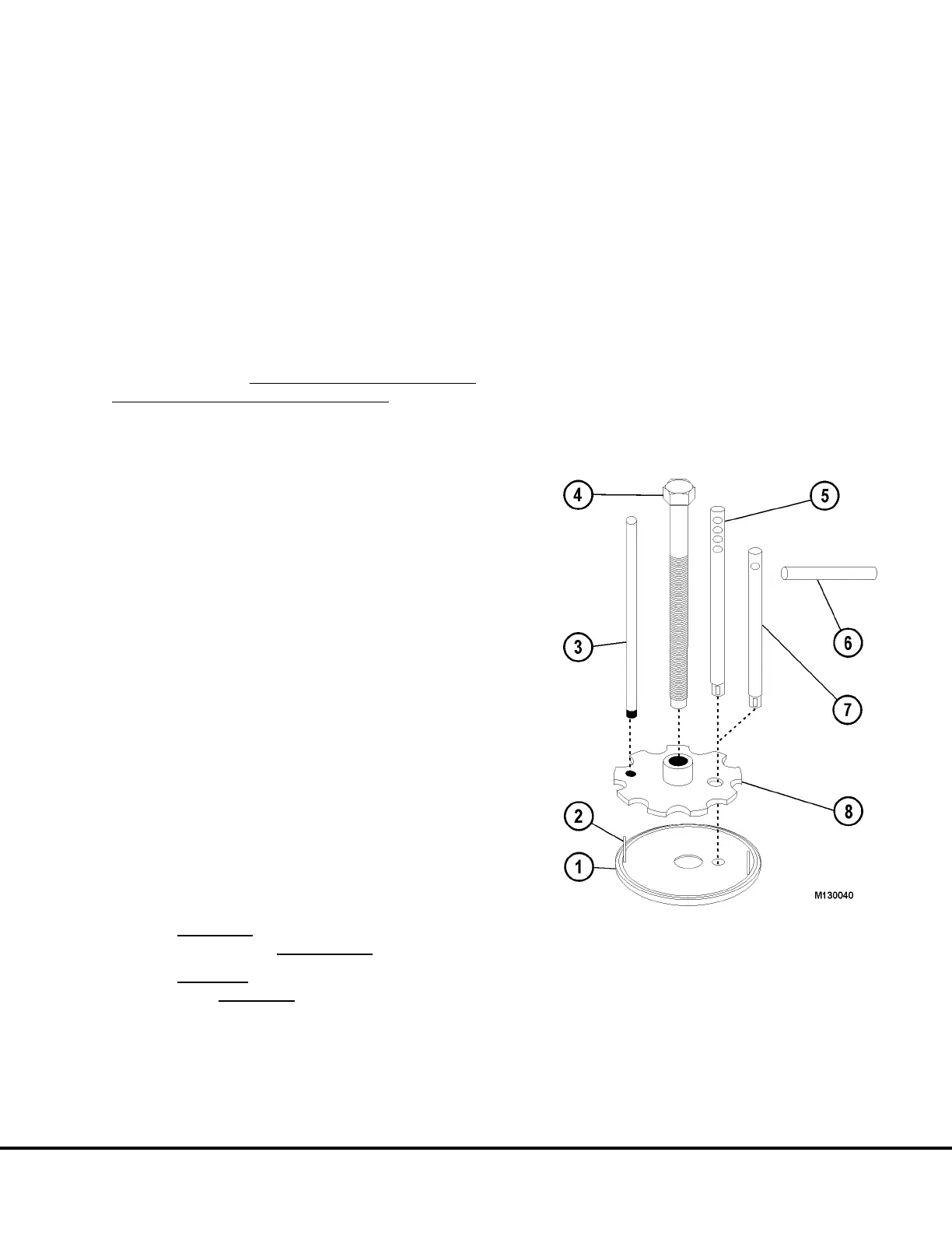
FIGURE 13-41.
1. Bottom Thrust Plate 5. Locating Rod (long)
2. Stator Indexing Pins 6. . Locating Pin
3. Guide Pin 7. Locating Rod (short)
4. Jack Screw 8. Pressure Plate
M13003 04/01 Niehoff Alternator Overhaul Manual M13-27
 Loading...


