HOIST PILOT VALVE
Removal
1. Place the hoist control lever in the body down
position. Make certain the body is in the full down
position and resting on the frame. Release the
hoist control lever to return the hoist valve spool
to the FLOAT position.
2. Disconnect hydraulic lines (3, Figure 8-13) at the
hoist pilot valve (1) located in the hydraulic com-
ponents cabinet at the rear of the cab. Remove
capscrews (5).
3. Loosen and unthread jam nut (8). Unthread
sleeve (9) until cotter pin (6) and pin (10) are
exposed.
4. Remove cotter pin and pin.
5. Remove the hoist pilot valve mounting hardware
(2) and remove valve from cabinet. Refer to hoist
pilot valve disassembly for repair instructions.
Installation
1. Place the hoist pilot valve (1, Figure 8-13) into
position on the mounting bracket. Secure valve
in place with mounting hardware (2).
2. Position hydraulic lines (3) over valve ports and
assemble fittings. Tighten hydraulic line connec-
tions securely.
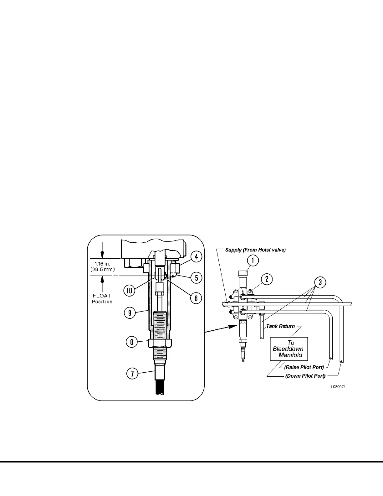
3. Place hoist control lever in spring-centered posi-
tion. Adjust pilot valve spool until the centerline
of the cable attachment hole extends 1.16 in.
(29.5 mm) from the face of the valve body.
4. Align control cable eye with pilot valve spool hole
and insert pin (10). Secure pin in place with cotter
pin (6).
5. Thread sleeve (9) upward until contact is made
with valve body. Move flange (4) into position and
secure in place with capscrews (5).
6. Thread jam nut (8) against sleeve. Tighten jam
nut securely.
7. Start the engine and check for proper hoist op-
eration. Observe for leaks.
FIGURE 8-13. HOIST PILOT VALVE & PIPING
(Located in Hydraulic Components Cabinet)
1. Hoist Pilot Valve
2. Mounting Hardware
3. Hydraulic Tubes
4. Flange
5. Capscrew
6. Cotter Pin
7. Control Cable
8. Jam Nut
9. Sleeve
10. Pin
L08024 Hoist Circuit Component Repair L8-9
 Loading...


