Relay Board 6 (RB6)
Relay board 6 (Figure 3-7) does not contain circuit
breakers or modular cards. Additional circuits may be
added by utilizing the empty relay sockets provided.
The following relays are installed on RB6:
• Back-up Lights & Horn Relay (K1)
• Engine Run/Ignition Relay (K2)
• Spare Socket (K3)
• Engine Retard Speed Relay (K4)
• Spare Socket (K5)
• Full Load Signal to PSC Relay (K6)
• 70% Load Signal to PSC Relay (K7)
• Spare Socket (K8)
Installing Additional Circuits
To add an additional circuit with a relay, connect the
wires as described below:
The control circuit for the relays are the “+ ” and “-”
terminals:
• “+ ” terminal is for positive voltage.
• “-” terminal is for grounding of the control circuit.
• Either circuit can be switched “open” or “closed”
to control the position of the relay.
The terminals of the switched circuit from the relay
contacts are labeled as follows:
• NC - Normally Closed
• COM - Common
• NO - Normally Open
> “COM” terminal is for the voltage source (pro-
tected by a circuit breaker) coming into the relay
which will supply the electrical power for the com-
ponent being controlled.
> “NC” terminal is connected (through the relay) to
the “COM” terminal when the relay is not ener-
gized (when the control circuit terminals “+ ” & “-”)
are not activated).
> “NO” terminal is connected (through the relay) to
the “COM” terminal when the relay is energized
(by the control circuits “+ ” & “-”) being ener-
gized).
If Relay Board 6 must be removed and replaced,
be certain to note correct orientation of board!
Improper orientation will result in incorrect hookup
to existing wire harness.
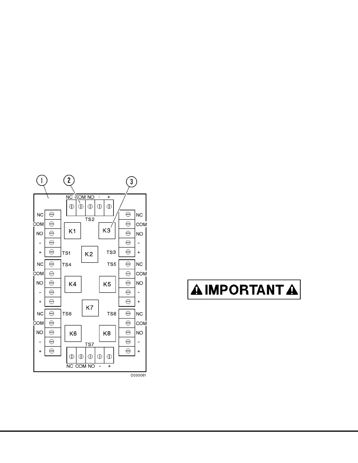
FIGURE 3-7. RELAY BOARD 6
1. Relay Board (RB6)
2. Terminal Strips (TS1 - TS8)
3. Relays (K1 - K8)
D3-12 24VDC System Components D03019 04/01
 Loading...


