HYDRAULIC SYSTEM FILTERS
HOIST CIRCUIT FILTER
The hoist circuit filter (Figure 9-1) is located on the fuel
tank below the right frame rail. The filter provides sec-
ondary filtering protection for hydraulic oil flowing to
the hoist valve and hoist circuit components.
An indicator switch (5) is designed to alert the operator
of filter restriction before actual bypass occurs. The
switch contacts close at 35 psid (240 kPa) to actuate a
warning lamp on the overhead display panel. Actual
filter bypass occurs at 50 psid (345 kPa).
NOTE: When the engine is initially started and the
hydraulic oil is cold, the warning lamp may actuate.
Allow the hydraulic system oil to reach operating tem-
perature before using the warning lamp as an indicator
to change the element.
Refer to Section P, Lubrication and Service for recom-
mended normal filter element replacement interval.
Earlier replacement may be required if the restriction
indicator lamp turns on.
Premature filter restriction may indicate a system com-
ponent failure and signal a service requirement before
extensive secondary damage can occur.
NOTE: An early indication of the filter warning light at
first installation may be due to restriction in the filter as
it cleans the system. Unless the fluid appears contami-
nated or has a strong foul odor, do not change the oil;
replace only the filter elment.
FILTER ELEMENT REPLACEMENT
Relieve pressure before disconnecting hydraulic
and other lines. Tighten all connections before
applying pressure.
Hydraulic fluid escaping under pressure can have
sufficient force to enter a person’s body by pene-
trating the skin and cause serious injury and pos-
sibly death if proper medical treatment by a
physician familiar with this injury is not received
immediately.
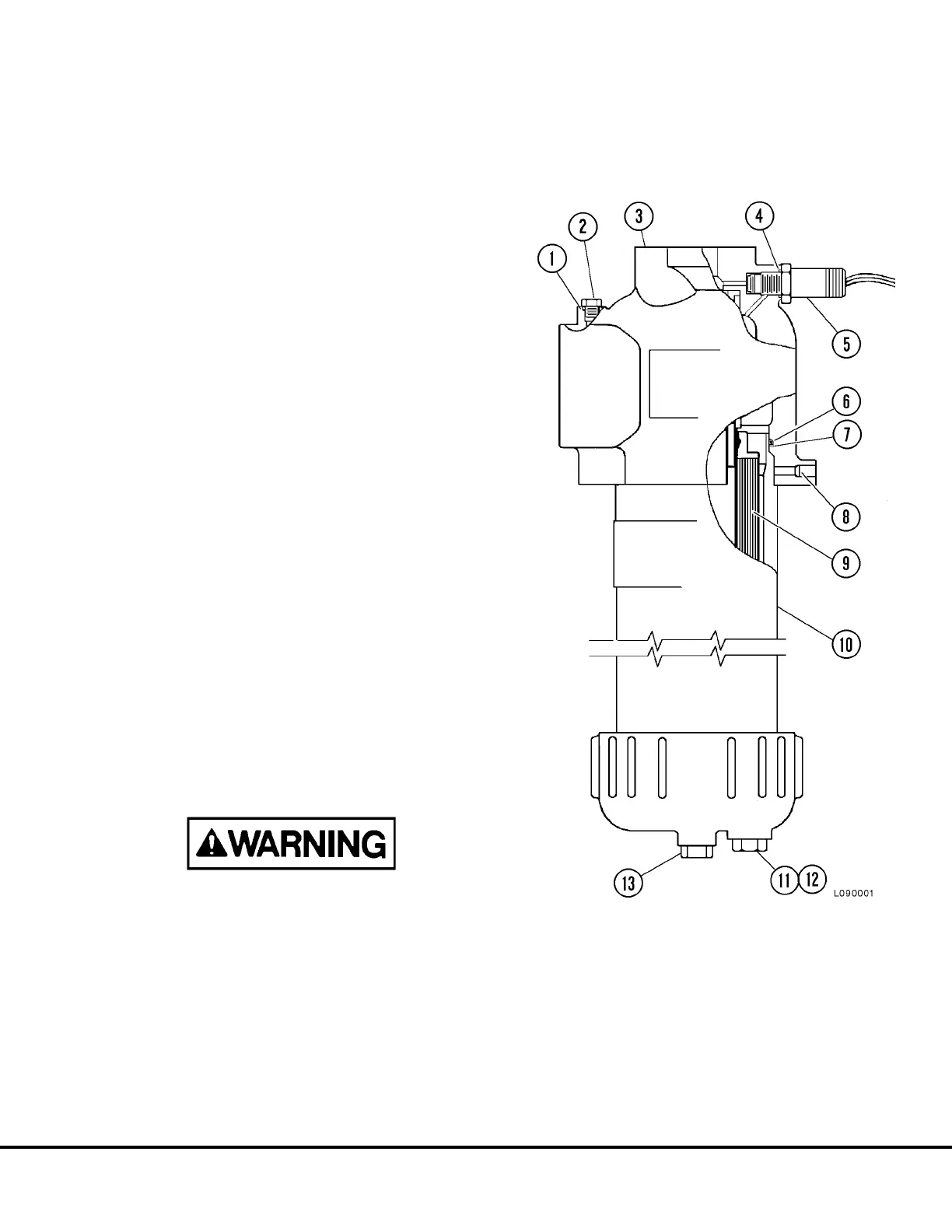
FIGURE 9-1. HOIST CIRCUIT FILTER
1. O-Ring
2. Plug
3. Filter Head
4. O-Ring
5. Indicator Switch
6. O-Ring
7. Backup Ring
8. Set Screw
9. Filter Element
10. Bowl
11. Bleed Plug
12. O-Ring
13. Bottom Plug
L09008 Hydraulic System Filters L9-1
 Loading...


