Diagnostic Information Display
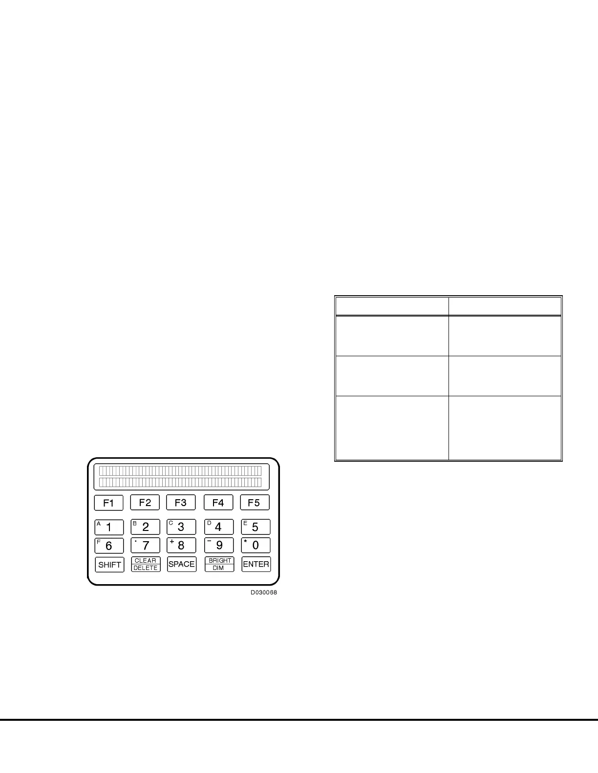
The 17FM558 Diagnostic Information Display (DID)
(Figure 2-2) is located in the cab, behind the passenger
seat. The display provides a means of communica-
tions with the TCI by service personnel. Information
from the PSC Aux Inverter is also routed through the
TCI for display on the DID.
The panel has two display lines, each line 40 charac-
ters long. The top line is the “message” line and is used
by the TCI to inform service personnel of the truck
systems and components status.
The bottom display line provides information in addi-
tion to the top line or relates to the keypad, displaying
possible selection options and display functions. The
keypad, located below the display lines is used by
service personnel to direct the activity of the TCI.
The display provides service and status information on
the various truck systems and the propulsion system
by displaying system status information or fault codes
as well as a description of the system status or a
problem on the top display line. Information on the
second display line may change to indicate what func-
tions are available by pressing the [F1] through [F5]
keys.
In addition, the DID panel can be used by to perform
the self-load test.
DID PANEL FAULT CODES
The Tables on the following pages list the possible
event codes which may be displayed on the DID panel
when accessed. Table I (below) describes restrictions
to operation of the propulsion and retarding systems
when a fault occurs for a particular code listed in
Tables II, III and IV.
NOTE: Event codes numbered 000 through 099 are
applicable to the PSC and are listed in Table II. Codes
numbered 100 through 199 are applicable to Inverter
1, and codes numbered 200 through 299 are applica-
ble to Inverter 2 and are listed in Table III. Codes
numbered 600 through 699 are applicable to the TCI
and are listed in Table IV.
The codes listed in the Tables are applicable to
Release 17 software.
RESTRICTION DEFINITION
No Power
No retarding Allowed
No propulsion allowed
No power on the link
No Propel
No propulsion allowed
Retarding allowed
Link power allowed
System Warning
If corrective action is
not taken, a more
restrictive event may
follow
No restrictions
TABLE I.
FIGURE 2-2. DIAGNOSTIC INFORMATION
DISPLAY
E02014 3/01 Electrical Propulsion System Components E2-5
 Loading...


