REAR SUSPENSIONS
The HYDRAIR
®
II suspensions are hydro-pneumatic
components containing oil and nitrogen gas. The oil an
gas in the four suspensions carry the gross truck
weight less wheels, spindles and final drive assembly.
The rear suspension cylinders consist of two basic
components; a suspension housing attached to the
rear axle housing, and a suspension rod attached to
the frame.
The HYDRAIR
®
II suspension cylinder requires only
normal care when handling as a unit. However, after
being disassembled these parts must be handled care-
fully to prevent damage to the machined surfaces.
Surfaces are machined to extremely close tolerances
and are precisely fitted. All parts must be completely
clean during assembly.
Removal
1. Remove capscrews, washers, and metal shield
(2, Figure 3-1) from the suspension.
2. Remove charging valve cap, (1, Figure 3-2)
loosen small hex (4) on charging valve and turn
counterclockwise three full turns to unseat valve
seal. Connect suspension charging kit.
Make certain only the swivel nut turns. Turning the
complete charging valve assembly may result in
the valve assembly being forced out of the suspen-
sion by the gas pressure inside.
3. If necessary, charge the suspension to be re-
moved with dry nitrogen until the rod is exposed
approximately 5.0 in. (127 mm).
4. Place stands or cribbing under the truck frame at
each hoist cylinder mount.
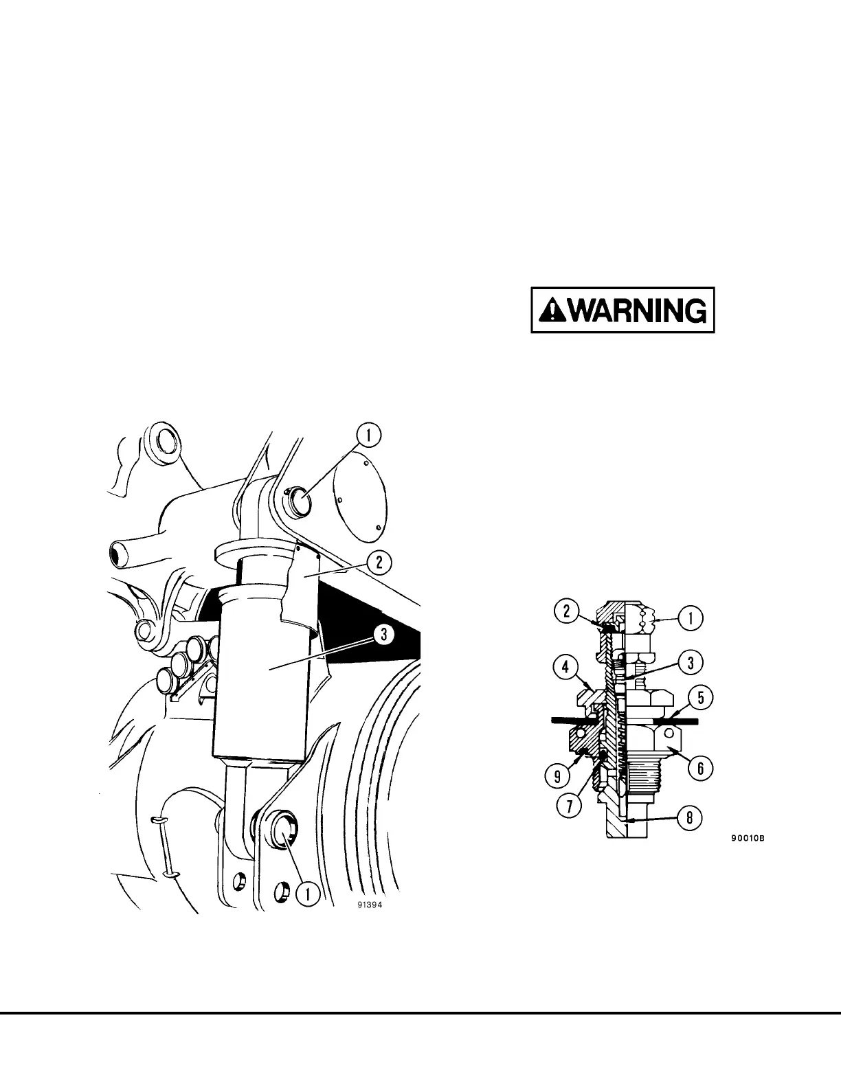
FIGURE 3-1. REAR SUSPENSION INSTALLATION
1. Mounting Pins
2. Piston Rod Shield
3. Suspension Cylinder
FIGURE 3-2. CHARGING VALVE
1. Valve Cap
2. Seal
3. Valve Core
4. Swivel Nut
5. Rubber Washer
6. Valve Body
7. O-ring
8. Valve Stem
9. O-ring
H03013 Rear Suspensions H3-1
 Loading...


