STEERING CIRCUIT
STEERING CIRCUIT OPERATION
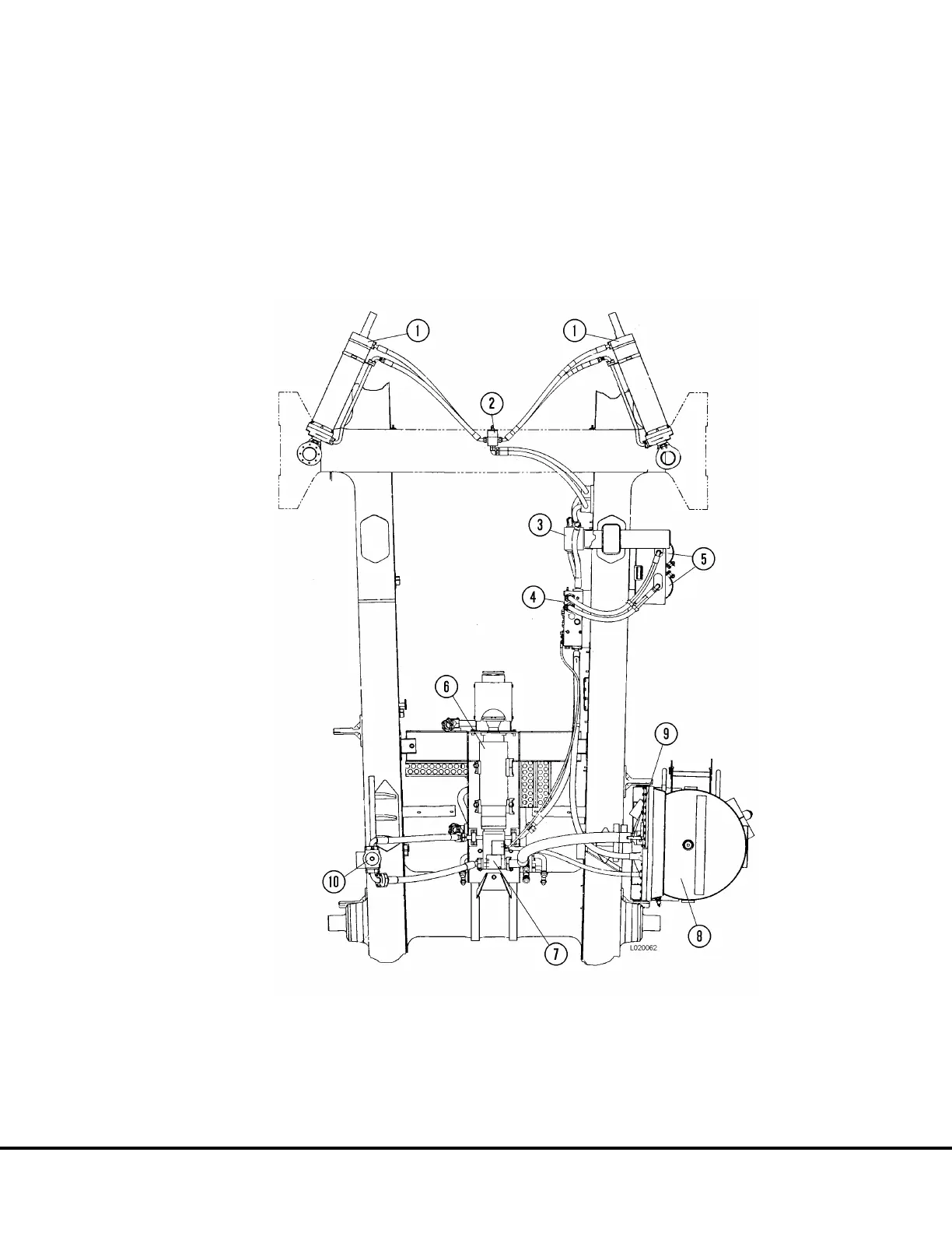
The steering/brake pump (7, Figure 4-1) supplies oil to
the bleeddown manifold (4) after passing through a
high pressure filter (10). If the filter element becomes
restricted, a warning indicator is activated at 40 psi (276
kPa) and oil will bypass the element at 50 psi (345 kPa).
System pressure is regulated to between 2750 psi (19.0
MPa) and 3025 psi (20.9 MPa) by an unloader valve
located on the bottom of the steering pump case.
FIGURE 4-1. STEERING SYSTEM COMPONENTS (Bottom View)
1. Steering Cylinders
2. Manifold
3. Flow Amplifier Valve
4. Bleeddown Manifold
5. Steering Circuit Accumulators
6. Hoist Circuit Pump
7. Steering/Brake Pump
8. Hydraulic Tank
9. Shut-off Valve
10. Steering/Brake Circuit Filter
L04031 Steering Circuit L4-1
 Loading...


