ENGINE/ALTERNATOR MATING
The following instructions must be followed to
ensure proper alignment and engine crankshaft
endplay. Failure to follow these instructions can
result in serious damage to the engine and/or
alternator.
General Instructions
• Never pry on the engine crankshaft damper!
• Loosen or remove fan belts prior to measuring
crankshaft end-play to insure that the crankshaft
moves easily and completely.
• When taking measurements, always take four
equally spaced readings and average them.
• Always measure from mating surface to mating
surface.
• References to crankshaft rotation; clockwise
(CW), or counterclockwise (CCW), is the direction
of rotation when looking at the front (damper end)
of engine.
• Crankshaft end-play :
0.13 - 0.38 mm (0.005 - 0.015 in.)
SERVICE DATA - Eccentricity & Runout Limits
Description T.I.R.
Max. Flywheel Housing Bore Eccentricity 0.66 mm
Max. Face Runout Flywheel Housing 0.25 mm
Max. Eccentricity of Flywheel
(Coupling Assy)
0.18 mm
Max. Axial Runout of Flywheel Face
(Coupling Assy)
0.25 mm
MEASURING PROCEDURE
1. Thoroughly clean the alternator housing mounting
surface, rotor drive adapter mounting surface and
flywheel housing adapter mounting surfaces.
2. With magnetic base mounted on the front of the
engine and the dial indicator on the front of the
crankshaft, measure total crankshaft end-play:
Verify end play is within 0.13 - 0.38 mm
(0.005 - 0.015 in.)
Record Total Crankshaft End-play:
3. Refer to Figure 4-4. Move the engine Crankshaft
to the rear of its end travel.
a. Carefully measure Dimension “C”
at four locations, 90° apart:
1st measurement:
2nd measurement:
3rd measurement:
4th measurement:
Dimension “C”: Average
b. Add 1/2 (one-half) of Total End-play ( Step 2).
c. Record (a + b) as;
“Measurement C”:
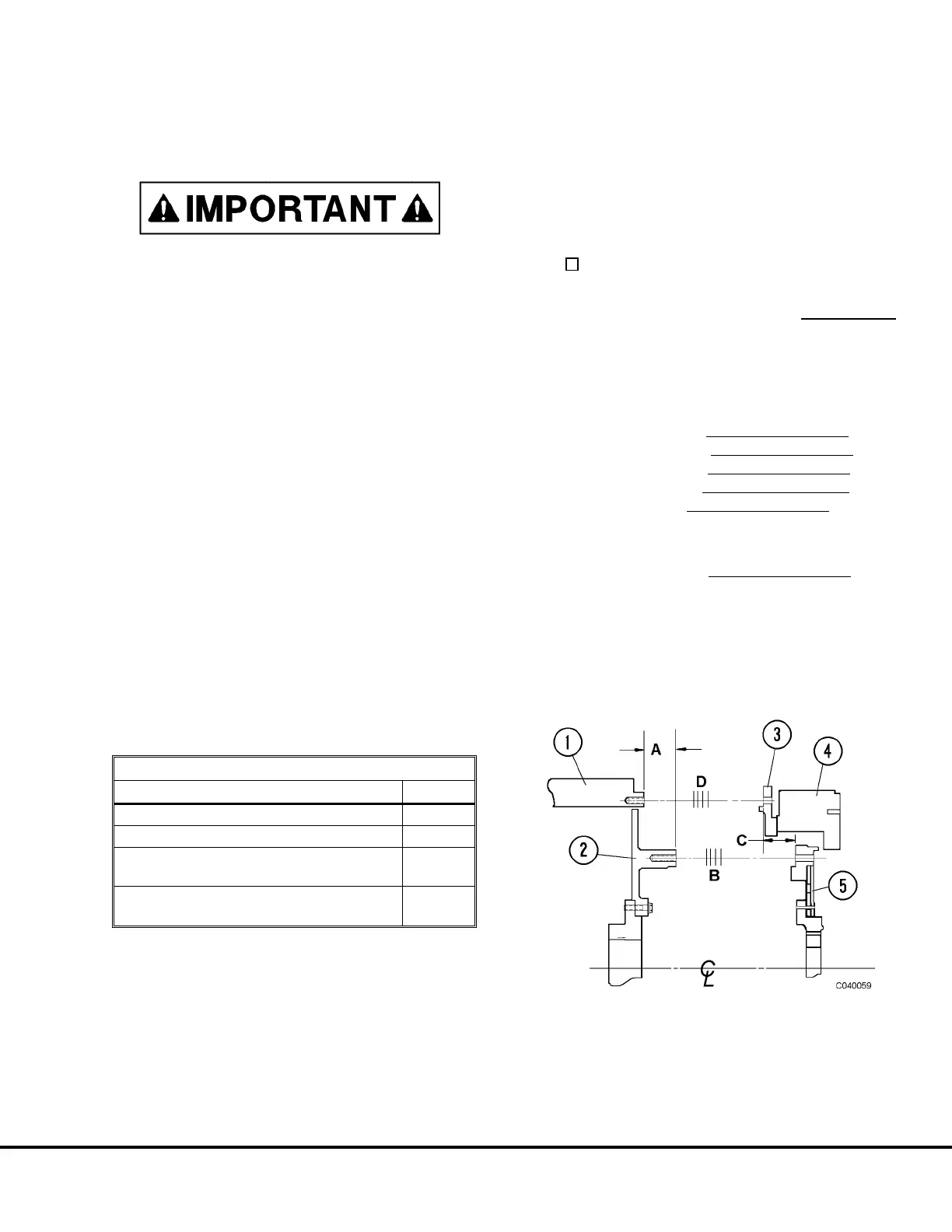
FIGURE 4-4. SHIM LOCATION
1. Alternator Housing
2. Alternator Rotor
3. Flywheel Housing Adapter
4. Engine Flywheel Housing
5. Engine Drive Ring
“A” - Dimension “A”
“B” - Drive Shims
“C” - Dimension “C”
“D” - Housing Shims
C04023 03/01 Power Train C4-3
 Loading...


