HEATER/AIR CONDITIONER
The heater assembly incorporates all the controls nec-
essary for regulating the cab interior temperature;
heated air during cold weather operation, outside air
during mild temperatures and cooled, de-humidified air
during warm weather operation.
The following information primarily describes the
heater system. Refer to Section M, “Air Conditioning
System” for detailed information concerning the com-
plete air conditioning system operation, repair, and
system recharging instructions.
OPERATION
Heat for the cab is provided by passing coolant from
the engine cooling system through a heater coil. Blow-
ers move air across the heating coil which warms the
air for heating or defrosting.
An engine driven freon compressor passes refrigerant
through an evaporator coil mounted in the same enclo-
sure. The same blowers used for heating move air
across the evaporator to provide cooled air through the
outlet vents.
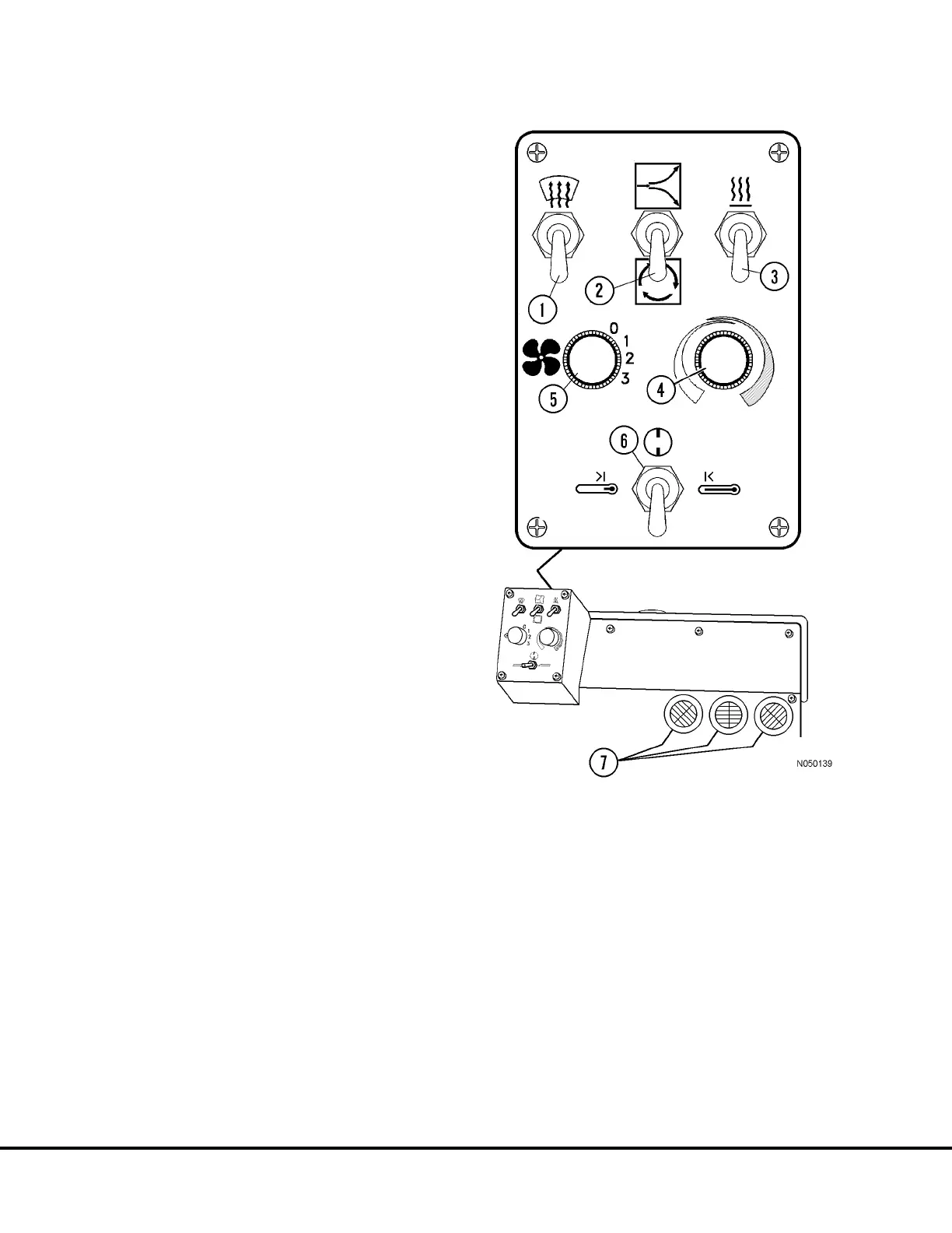
All heater and air conditioner controls are mounted on
a pod on the face of the enclosure. Refer to Figure 4-2
for the following:
• Defroster Switch (1): This is a 2-position toggle
switch; “down ” is "OFF". “Up” provides air flow
through the defroster vents.
• Outside/Inside Air Control Switch (2): This is a
2-position toggle switch; “down” recirculates cab
air. “Up” allows outside air to flow through heater
or air conditioner coils.
• Heat Vent Control Switch (3): This is a 2-position
toggle switch; “down ” is "OFF". “Up” provides
heated air flow to the cab floor.
• Temperature Control Knob (4): This is a variable
rotary control. Rotating the knob counterclock-
wise (blue arrow) will select increasingly cooler
temperatures. Rotating the knob clockwise (red
arrow) selects increasingly warmer temperatures.
• Fan Control (5); This is a 3-position rotary switch;
rotate knob to select low, medium, or high fan
speed.
• Heater/Air Conditioner Selector Switch (6): This is
a three position switch; the right position activates
the heater, the left position activates the air condi-
tioner, and the center position is "OFF"
FIGURE 4-2. HEATER/AIR CONDITIONER
CONTROLS
1. Defroster Control
2. Outside/Inside Air
Control
3. Heat Control
4. Temperature Control
5. Fan Control
6. Heater/Air
Conditioner Selector
7. Outlet Vents
N4-2 Operator Comfort N04020
 Loading...


