2. Remove charging valve cap. Turn the charging
valve swivel nut (4, Figure 4-3) counterclockwise
three full turns to unseat valve. DO NOT TURN
LARGE HEX (6). The valve body must not be
loosened until ALL nitrogen pressure has been
vented from the suspension.
3. Depress the charging valve core to release nitro-
gen pressure from the suspension. When all ni-
trogen has been vented to atmosphere, the
suspension should have collapsed slowly and be
seated solidly on the support blocks. Remove top
fill plug next to charging valve (Figure 4-2).
4. Fill the suspension with clean HYDRAIR
®
oil until
the cylinder is full to top of fill plug bore. Drip pans
should be used and all spillage cleaned from
outside of suspension. Allow suspension to stand
for at least 15 minutes to clear any trapped nitro-
gen and/or bubbles from the oil. Add more sus-
pension oil if necessary. Replace fill plug using a
new O-ring.
Front Suspension Nitrogen Charging
Lifting equipment (crane or hydraulic jacks) must
be of sufficient capacity to lift the truck weight. Be
certain that all personnel are clear of lift area be-
fore lift is started.
1. With nitrogen charging blocks at hand (Figure
4-2), use crane or jacks to raise the truck to
provide clearance for the blocks.
2. Remove oiling blocks and install nitrogen charg-
ing blocks. Secure blocks so they will not fly free.
Lower truck frame until the blocks are firmly and
squarely seated between the spindle and the
cylinder housing.
NOTE: Use caution to prevent damage to plated cyl-
inder surfaces and oil seals.
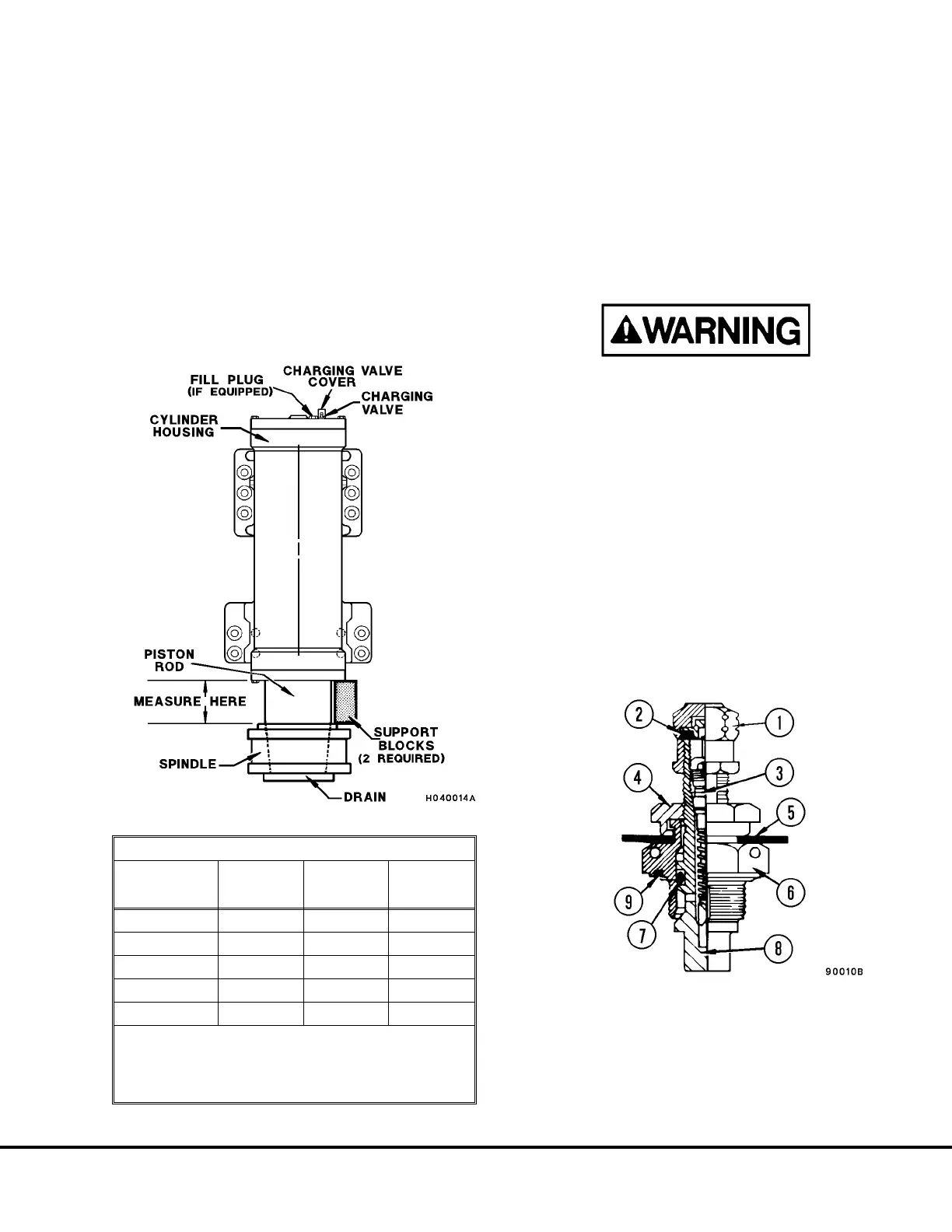
FIGURE 4-2. FRONT SUSPENSION
FRONT SUSPENSION DIMENSIONS (EMPTY)
TRUCK
MODEL
& OPTIONS
OILING
HEIGHT
in. (mm)
CHARGING
HEIGHT
in. (mm)
CHARGING
PRESSURE
psi (kPa)
730E* 1.5 (38.1) 9.0 (229) 400 (2758)
830E* 1.0 (25.4) 9.0 (229) 390 (2689)
830E** 1.0 (25.4) 9.0 (229) 410 (2827)
930E* 1.0 (25.4) 9.0 (229) 440 (3034)
930E-2* 1.0 (25.4) 9.0 (229) 425 (2930)
* with Standard Rock Body
** with Combination Body /Tailgate
Note: If truck starts to lift off blocks before charging
pressure is attained, STOP CHARGING.
FIGURE 4-3. CHARGING VALVE
1. Valve Cap
2. Seal
3. Valve Core
4. Swivel Nut
5. Rubber Washer
6. Valve Body
7. O-Ring
8. Valve Stem
9. O-ring
H04005 9/99 Oiling and Charging Procedures H4-3
730E, 830E, and 930E
 Loading...


