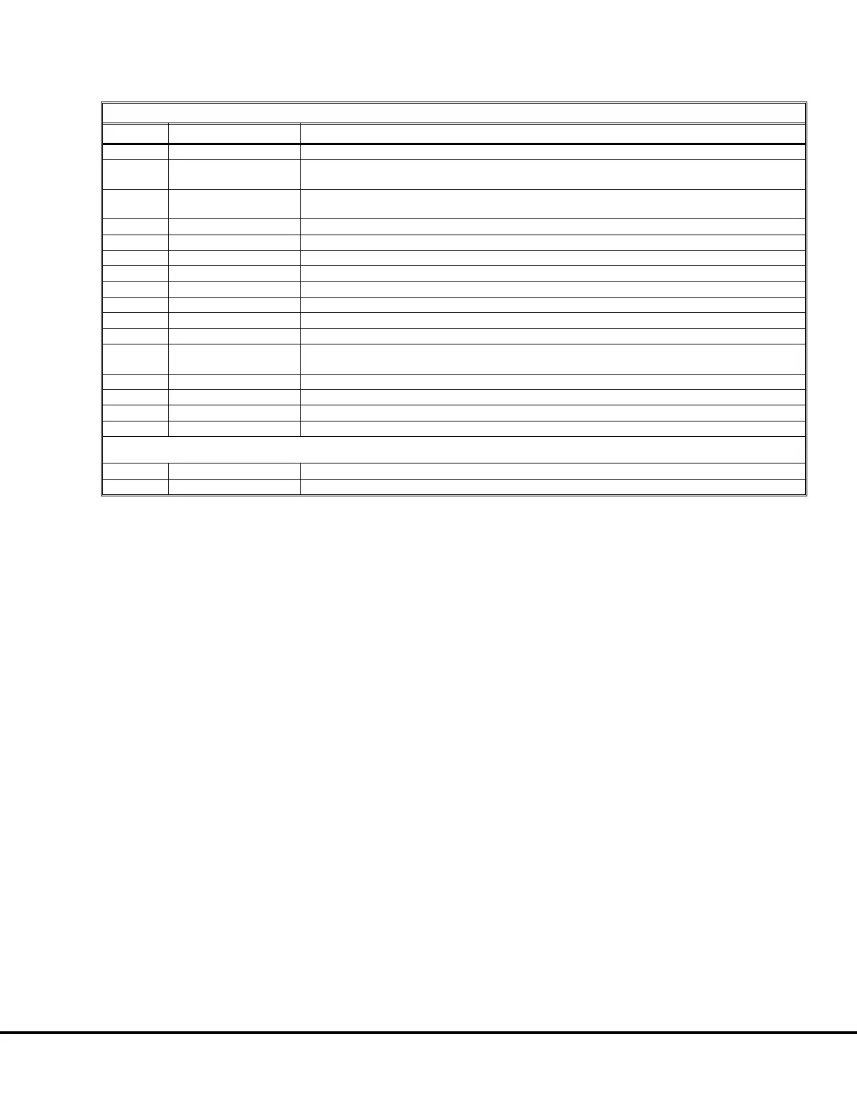
TABLE III: TCI DIGITAL INPUT TESTS
STEP DO NAME DESCRIPTION
1 LAMPTEST Lamp Test Switch (Overhead Display - all lamps except last two rows should illuminate)
2 ENGCAUTION
Check Engine Caution Lamp (Jumper circuit 419M @ TB30 to ground to illuminate overhead lamp)
(Note: If equipped with Komatsu engine, ENGCAUTION will not be highlighted on PTU.)
3 ENGWARN
Stop Engine Warning Lamp (Jumper circuit 509 @ TB30 to ground to illuminate overhead lamp)
If equipped with Komatsu engine, jumper 528A @ TB32 to ground to illuminate 2nd indicator lamp.)
4 RESET Clear/delete pushbutton switch on Console
5 RESTSW Rest Switch (Place switch in RESTposition to activate)
6 REVREQ Selector Switch in REVERSE position
7 FORREQ Selector Switch in FORWARD position
8 ENGKILL Engine Shutdown Switch (Depress switch on console)
9 DATASTORE Data Store Switch (on front of console - push to activate)
10 BODYDWN Body Up Switch (Activated when body is down)
11 PRKBRKSW Park Brake Switch (Highlighted with switch ON)
12 PRKBRKFDBK
Park Brake Feedback Signal (Highlighted - Jumper circuit 73S on Park Brake Pressure switch, on
brake manifold in brake cabinet to ground to remove highlight.)
13 ENGSTRTREQ Engine Start Request (Refer to Digital Input for check procedure)
14 RSC Retard Speed Control Switch (on console - pull up to highlight)
15 OVERPAYLD Truck Overloaded (Jumper circuit 72IP@TB29 to circuit 712 @ TB32)
16 CONTROLON Control Power ON (Do not check)
Refer to procedure step 3. before performing the following checks (RB2 circuit breakers must be OFF):
17 MIDPAYLD Truck at 70% Payload (Jumper 73MS @TB25 to ground.)
18 FULLPAYLD Truck Fully Loaded (Jumper 73LS @TB25 to ground.)
E03015 3/01 AC Drive System Electrical Checkout Procedure E3-17
(Release 17 Software)

 Loading...


