Disassembly
1. Remove charging valve (3, Figure 6-4).
2. Remove gland (4).
Note: Figure 6-5 illustrates a tool that can be fabricated
locally to aid in removing the gland.
3. Remove plugs and/or adaptor (10 & 11). Using a
round rod, push piston (6) out of accumulator.
4. Remove piston rings (7) and seal (8).
Cleaning and Inspection
1. Clean parts using fresh cleaning solvent, lint free
wiping cloth and filtered compressed air. All parts
must be absolutely free of any foreign matter
larger than 3 microns.
2. Inspect piston for damage. If scored or otherwise
damaged, replace with a new part.
3. Minor defects in the housing bore may be cor-
rected by honing.
a. Measure the bore at several places along the
length of the housing. Make two measure-
ments, 90° apart at each point to verify tube is
not out-of-round.
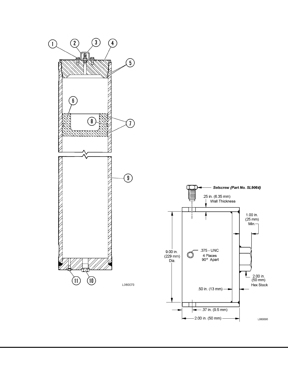
FIGURE 6-4. ACCUMULATOR ASSEMBLY
1. Capscrew
2. Cover
3. Charging Valve
4. Gland
5. O-ring & Backup Ring
6. Piston
7. Bearing
8. “T” Ring Seal
9. Housing
10. Plug (or Adaptor)
11. Plug
FIGURE 6-5. GLAND REMOVAL TOOL
(Fabricate Locally)
L06021 Steering Circuit Component Repair L6-3

 Loading...


