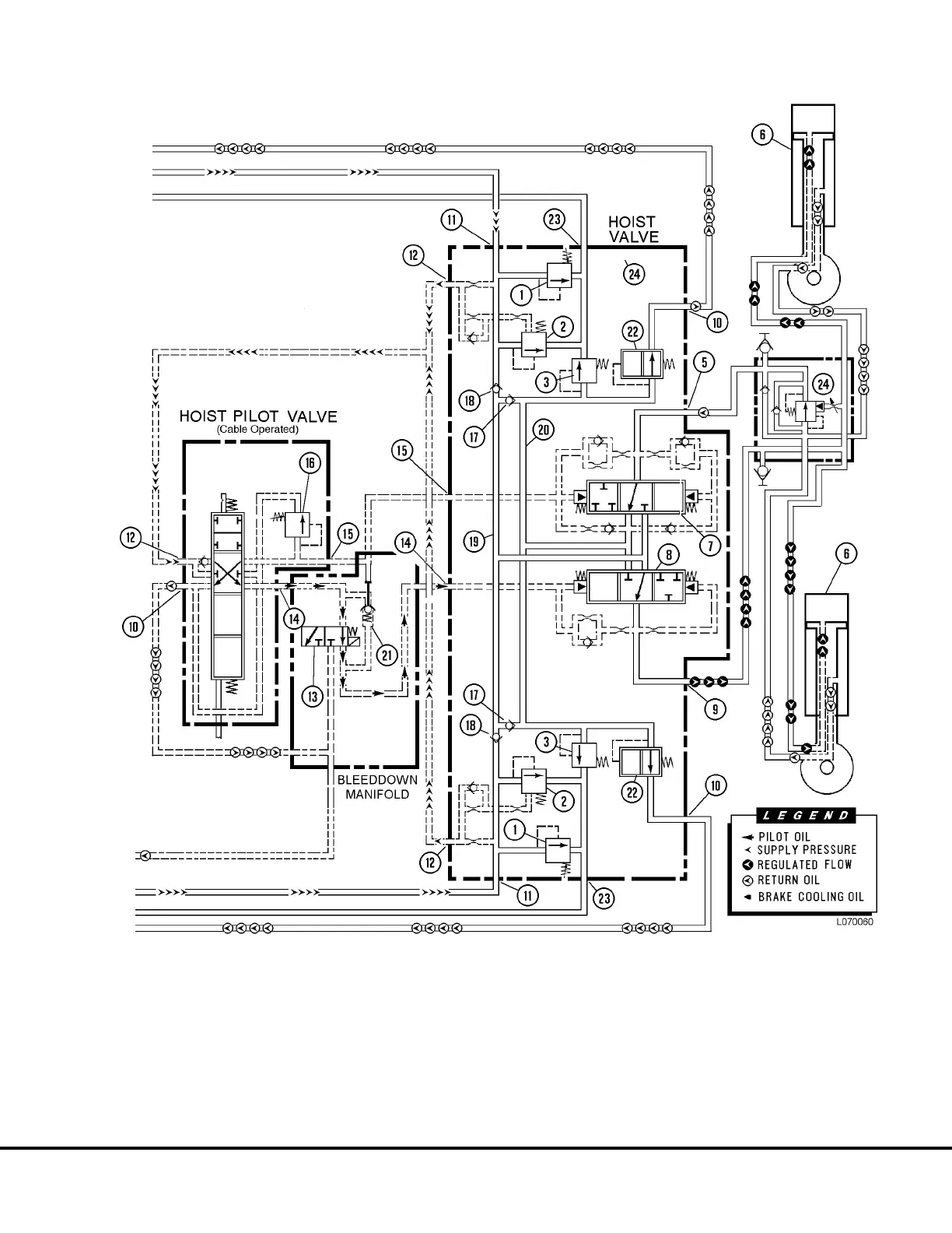
FIGURE 7-6. POWER UP POSITION
1. Hoist Relief Valve (2500 psi)
2. Flow Control Valve
3. Secondary Low Press. Valve (250
psi)
4. Snubber Valve
5. Rod End Work Port
6. Hoist Cylinders
7. Rod End Spool
8. Head End Spool
10. Return Port
11. Supply Port
12. Pilot Supply Port
13. Hoist Limit Solenoid
14. Raise Pilot Port
15. Down Pilot Port
16. Power Down Relief
Valve (1500 psi)
17. Anti-void Check Valve
18. Load Check Valve
19. High Pressure Passage
20. Low Pressure Passage
21. Pilot Operated Check Valve
22. Primary Low Pressure Valve (26 psi)
23. Brake Cooling Port
24. Overcenter Manifold
L07023 Hoist Circuit L7-9

 Loading...


