9.2.1 Device prole CiA 402
For control via device prole CiA 402, the parameters listed in the following can be mapped to
network register.
Details
•
The mapping entry for the CiA 402 control word is 0x60400010.
•
The mapping entry for the CiA 402 status word is 0x60410010.
•
General informaon about the process of data mapping can be found in the chapter of the
same name for the corresponding network.
•
For further CiA 402 parameters, see chapter "Device prole CiA 402". ^ 469
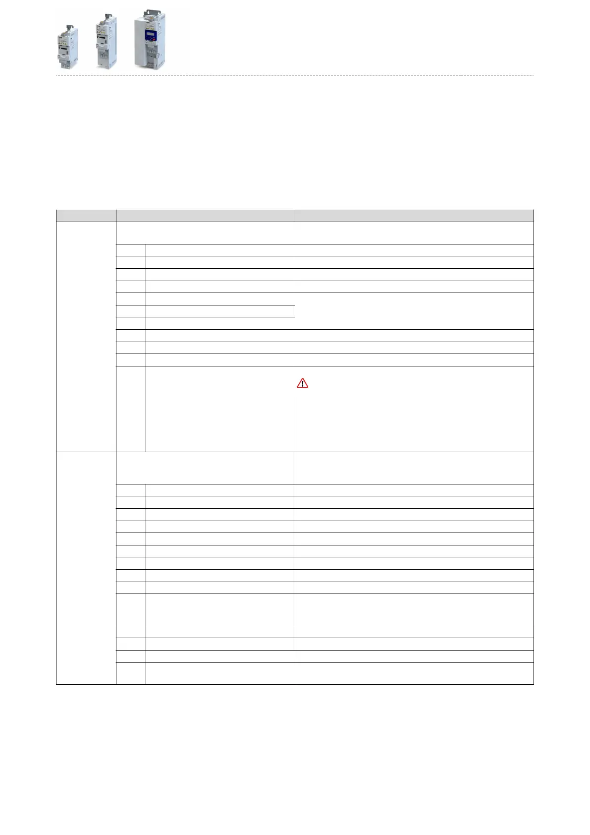
Parameter Name / value range / [default seng] Info
0x6040 CiA: Controlword
0 ... [0] ... 65535
Mappable CiA 402 control word with bit assignment according to device
prole CiA 402.
Bit 0 Switch on 1 = switch-on
Bit 1 Enable voltage 1 = DC bus: Establish readiness for operaon
Bit 2 Quick stop 0 = acvate quick stop
Bit 3 Enable operaon 1 = enable operaon
Bit 4 Operaon mode specic Bits are not supported.
Bit 5 Operaon mode specic
Bit 6 Operaon mode specic
Bit 7 Fault reset 0-1 edge = reset error
Bit 8 Halt (from version 04.00) 1 = stop motor (ramping down to frequency setpoint 0 Hz)
Bit 9 Operaon mode specic Operang mode dependent
Bit 14 Release holding brake 1 = releasing holding brake manually
CAUTION!
•
The manually triggered "Release holding brake" command has a direct
impact on the "Release holding brake [115]" trigger. Thus, the holding
brake can be manually released if the power secon is switched o.
•
The responsibility for a manual release of the holding brake has the
external trigger source for the "Release holding brake" command.
4Holding brake control ^ 472
0x6041
(P780.00)
CiA: Statusword
(CiA: Statusword)
•
Read only
Mappable CiA 402 status word with bit assignment according to device
prole CiA 402.
Bit 0 Ready to switch on 1 ≡ drive ready to start
Bit 1 Switched on 1 ≡ drive switched-on
Bit 2 Operaon enabled 1 ≡ operaon enabled
Bit 3 Fault 1 ≡ fault or trouble acve
Bit 4 Voltage enabled 1 ≡ DC bus ready for operaon
Bit 5 Quick stop 0 ≡ quick stop acve
Bit 6 Switch on disabled 1 ≡ operaon inhibited
Bit 7 Warning 1 ≡ warning acve
Bit 8 RPDOs deacvated 1 ≡ cyclic PDOs have been deacvated.
Bit 9 Remote 1 ≡ inverter can receive commands via network.
•
Bit is not set in the operang mode 0x6060 (P301.00) = "MS: Velocity
mode [-2]".
Bit 10 Target reached 1 ≡ the actual posion is in the window.
Bit 11 Internal limit acve 1 ≡ internal limitaon of a setpoint acve.
Bit 14 Holding brake released 1 ≡ holding brake released
Bit 15 Safe torque o (STO) not acve 0 ≡ STO acve
1 ≡ STO not acve
Conguring the network
Predened process data words
Device prole CiA 402
247
 Loading...


