14.15 Conguraon of digital outputs
Parameter Name / value range / [default seng] Info
0x404D:003
(P608.03)
PID alarms: Monitoring bandwidth PID feedback sig-
nal
(PID alarms: Bandw. feedback)
0.00 ... [2.00] ... 100.00 %
•
From version 04.00
Hysteresis for status signal "PID feedback = setpoint [73]".
•
100 % ≡ congured variable input range
•
Example: Variable input range 0 ... 10 V: 2 % ≡ 0.2 V
•
The status signal "PID feedback = setpoint [73]" is TRUE if the control-
led variable fed back = process controller setpoint (± hysteresis set
here).
•
The status signal can be assigned to the relay, a digital output of the
NetWordOUT1 status word. 4Conguraon of digital outputs ^ 602
14.15.1 Relay
Sengs for the relay.
Relay is not suitable for direct switching of a electromechanical holding brake!
Use a corresponding suppressor circuit in case of an inducve or capacive
load!
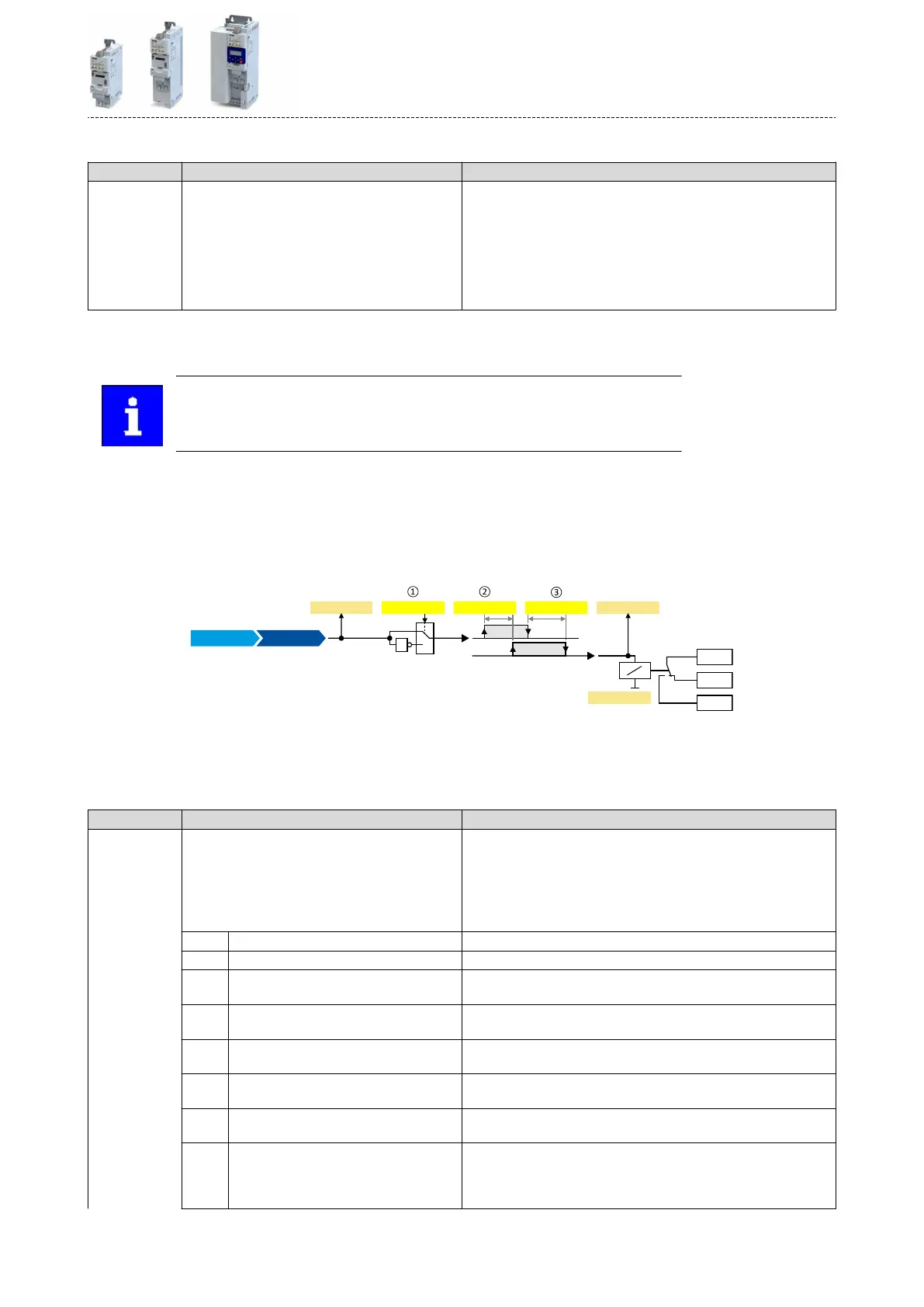
Details
The relay is controlled with the trigger selected in 0x2634:001 (P420.01).
The following sengs are possible for the relay:
•
Inversion
①
•
Switch-on delay
②
•
Cutout delay
③
COM
NC
NO
0x4018:0050x4018:006
1
0
1
0x2635 001: 0x4018 004: 0x4018:003
0x2634:001
X9
0x4018:007
Trigger
Diagnosc parameters:
•
The logic status of the trigger signal is displayed in 0x4018:006.
•
The logic status of the relay is displayed in 0x4018:005.
•
The current switching cycles of the relay are shown in 0x4018:007.
Parameter Name / value range / [default seng] Info
0x2634:001
(P420.01)
Digital outputs funcon: Relay
(Dig.out.funcon: Relay funcon)
Assignment of a trigger to the relay.
Trigger = FALSE: X9/NO-COM open and NC-COM closed.
Trigger = TRUE: X9/NO-COM closed and NC-COM open.
Notes:
•
An inversion set in 0x2635:001 (P421.01)is taken into consideraon
here.
0 Not connected No trigger assigned (trigger is constantly FALSE).
1 Constant TRUE Trigger is constantly TRUE.
11 Digital input 1 State of X3/DI1, taking an inversion set in 0x2632:001 (P411.01) into
consideraon.
12 Digital input 2 State of X3/DI2, taking an inversion set in 0x2632:002 (P411.02) into
consideraon.
13 Digital input 3 State of X3/DI3, taking an inversion set in 0x2632:003 (P411.03) into
consideraon.
14 Digital input 4 State of X3/DI4, taking an inversion set in 0x2632:004 (P411.04) into
consideraon.
15 Digital input 5 State of X3/DI5, taking an inversion set in 0x2632:005 (P411.05) into
consideraon.
16 Digital input 6 State of X3/DI6, taking an inversion set in 0x2632:006 (P411.06) into
consideraon.
Digital input 6 is only available in the Control Unit (CU) with applicaon
I/O.
Flexible I/O conguraon
Conguraon of digital outputs
Relay
603
 Loading...


