4.4.4 PROFIBUS
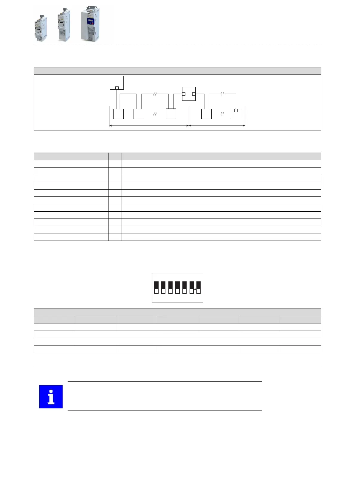
Typical topologies
Line with repeater
M
R
1
S1n
S12S11
2
X1
S21
S2n
R
R R
R
M Master X Repeater
S Slave R Acvated bus terminang resistor
Terminal descripon PROFIBUS
Connecon X226
Connecon type Sub-D 9p
Min. cable cross-secon mm² -
Min. cable cross-secon AWG -
Max. cable cross-secon mm² -
Max. cable cross-secon AWG -
Stripping length mm -
Stripping length inch -
Tightening torque Nm -
Tightening torque lb-in -
Required tool -
Basic network sengs
Use the DIP switch to set the staon address.
The baud rate is detected automacally.
Address
O
N
32
16 8
4
64
2 1
PROFIBUS
PROFIBUS staon address
64 32 16 8 4 2 1
OFF OFF OFF OFF OFF OFF OFF
Value from parameter
Staon address - example:
OFF OFF ON OFF ON ON ON
Staon address = 16 + 4 + 2 + 1 = 23
Do not set staon address = 126 and staon address = 127. These staon addresses are invalid.
Bold print = default seng
The network must be terminated with a resistor at the physically rst and last
node.
Acvate the bus terminang resistor at these nodes in the bus connecon plug.
Electrical installaon
Networks
PROFIBUS
67
 Loading...


