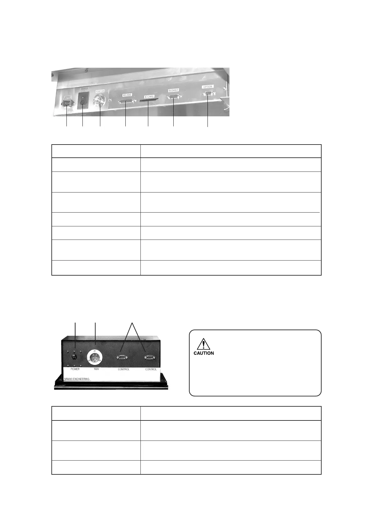
— 1.7 —
Right-hand side face of the electrical box
Blower unit
Name Function
1 Power switch Used to turn on/off the power to the blower unit. Normally, it is set to the
on position. Turn it off when conducting maintenance works.
2 Signal wire connector To be connected, using a signal wire, to the signal wire connector for the
blower on the electrical box.
3Power connector The power cable for the blower is connected to this connector.
Name Function
1Power connector To be connected to the power cable of the plotter.
2 Main power switch Used to turn on/off the main power of this device. Normally set it to the on
state. Set it to the off state when conducting maintenance works.
3 Foot switch connector Foot switch for vacuum is connected to this connector. (Optional)
Note: The shape of this connector may differ from that shown in the photograph.
4 RS-232C interface To be connected to a personal computer using an interface cable.
5 IC card slot To be used when conducting maintenance works.
6 Signal wire connector for To be connected to the blower unit using a signal wire.
blower
7 Optional connector An optional device is connected to this connector.
12 3 4 5 6 7
12 3
•When using a separately sold
blower that differs from the stan-
dard blower, there may be no
power switch. For the output
voltage, refer to the value display
on the blower unit.
 Loading...