Setting cutting conditions
The following describes how to establish cutting conditions for cutter 2 (tangential cutter) as an
example.
Once you have set cutting conditions, execute the [TEST CUT] function to check whether or not the
cutting conditions are proper. (See page 2.35.)
1 Select the head and the tool in the
[TOOL SELECT]. (See page 2.26.)
Select B for the head and cutter 2 for the
tool.
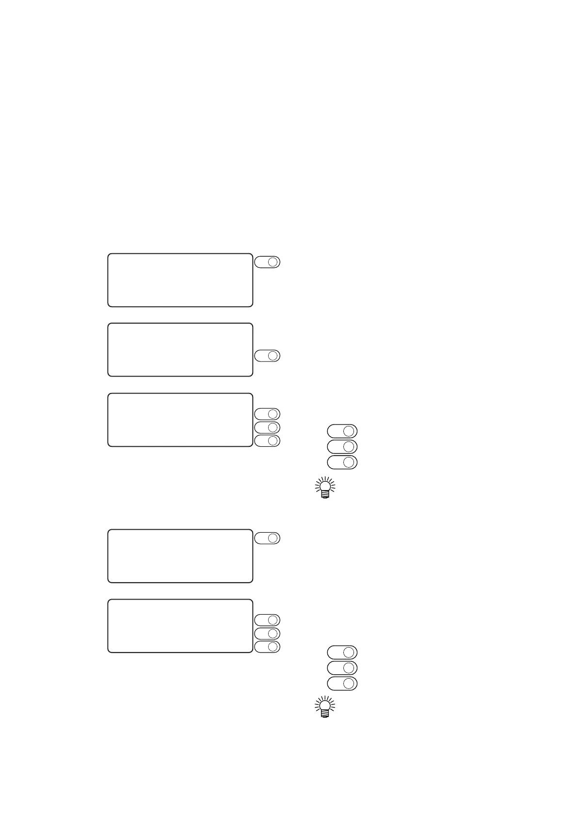
2 Invoke the 1st page of the LOCAL
MENU.
3 Select the [CONDITION].
Select the CONDITION, and the cutting
conditions for the cutter 2 will appear on
the screen.
4 Set the speed, pressure and accelera-
tion to adequate values.
F1
+
..... Input a speed.
F2
+
..... Input a pressure.
F3
+
..... Input an acceleration.
• If the “– (minus)” key of the respec-
tive function keys is pressed, a
previous value is indicated on the
display.
5 Invoke the 2nd page of the cutting con-
ditions screen for cutter 2.
6 Set the [START CORRECTION],
[END CORRECTION] and [UP
ANGLE] to adequate values.
F1
+
..... Input a start correction.
F2
+
..... Input an end correction.
F3
+
..... Input an up angle.
• If the “– (minus)” key of the respec-
tive function keys is pressed, a
previous value is indicated on the
display.
[ LOCAL ] 1 / 4
TOOL SELECT ———>
CONDITION ———>
TEST CUT ———>
PAGE
+
[ LOCAL ] 1 / 4
TOOL SELECT ———>
CONDITION ———>
TEST CUT ———>
< CUTTER 2 > 1 / 4
SPEED ∗40 cm/s >
PRESSURE ∗400 g >
ACCELE ∗0.4 G >
< CUTTER 2 > 1 / 4
SPEED 50 cm/s >
PRESSURE 900 g >
ACCELE 0.3 G >
F2
+
F3
+
F1
+
F2
+
PAGE
+
< CUTTER 2 > 2 / 4
F OFFSET ∗0.50 mm >
E OFFSET ∗0.50 mm >
UP ANGLE ∗30° >
F3
+
F1
+
F2
+
 Loading...