Addendum to V Series Operating Instructions 1 - 9
Continuous Cardiac Output (CCO) & Continuous Hemodynamics (Optional) Digital Tiles
3. Connect the other end of the serial cable to serial port on the VDI module.
4. Verify the current VDI mode is configured to Vigilance.
NOTE: Refer to "Changing VDI Modes" on page 5-4 of the V Series Operating
Instructions for additional information.
5. Turn on the Edwards monitor.
1.3.3 Configuring the Edwards Monitor Serial Port
Before configuring the V 12/V 21 monitor to display SvO2, the Edwards monitor serial port must be
properly configured to communicate bidirectionally with the V 12/V 21. Using the operating
instructions from the Edwards monitor, verify the following:
1.4 Digital Tiles
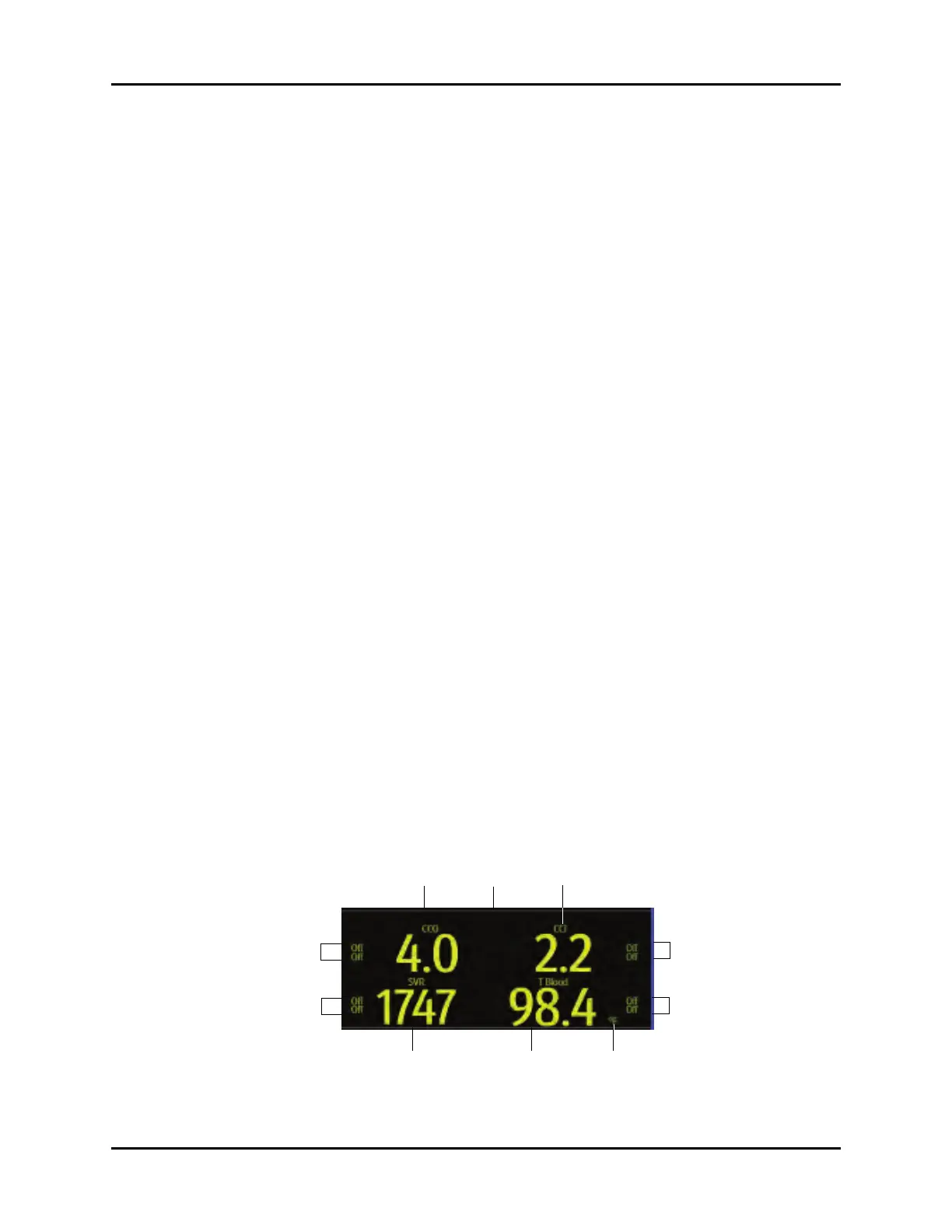
1.4.1 CCO Digital Tile Layout
The CCO digital tile displays:
1. CCO value
2. Message area
3. CCI value
4. CCI alarm limits
5. T Blood alarm limits
6. Units of measure
7. T Blood value
8. SVR or SVRI value
9. SVR or SVRI alarm limits
10. CCO alarm limits
FIGURE 1-6 Exa
mple CCO Digital Tile (with SVR enabled)
Baud Rate 19200
Parity None
Stop Bits 1
Data Bits 8
Flow Control 2 Seconds
 Loading...