146
Connecting to the Host’s RS-422A/485 Port
Section 5-2
5-2-7 Setting the Terminal Resistance for RS–422A/485 Communica-
tions
The serial port B connector of the NT31/NT31C has a terminal resistance setting
terminal (TRM).
In RS-422A/485 communications, a terminal resistor must be set at the device at
the end of the communication cable, but not at any other device.
The NT31/NT31C has a built-in terminal resistor, and whether or not the terminal
resistance is applied is set by the wiring at the terminal resistance setting terminals
(pins No. 9 and 10 of serial port B). The terminal resistance is 120 Ω. When carry-
ing out RS-422A/485 communications using serial port B, short between terminals
No. 9 and 10 at the NT31/NT31C at the end of the RS-422A/485 cable. Leave
terminals No. 9 and 10 open at NT31/NT31C units other than the one at the end of
the cable.
When not using RS-422A/485 communications, the terminal resistance setting is
ineffective.
In order to set the terminal resistance, wiring work is required at the cable’s con-
nector: carry out the wiring correctly by referring to APPENDIX E “Making the
Cable”, page 661.
Abbreviation
FG
-
-
TRM
RDB (+)
SDB (+)
-
-
-
Pin number
Connector
hood
-
9
10
11
12
-
25
Terminal resistor setting
Pin Nos. 9 and 10 Function
Shorted
Terminal resistance is applied.
Short only at the NT31/NT31C connected to the end of an
RS-422A/485 cable.
Open
Terminal resistance is not applied.
Leave the terminals open when connecting an NT31/NT31C
anywhere other than at the end of the RS-422A/485 cable.
Note Before connecting or disconnecting cables between devices, make sure that the
power supply to all of the connected devices (NT31/NT31C, PC, etc.) is OFF.
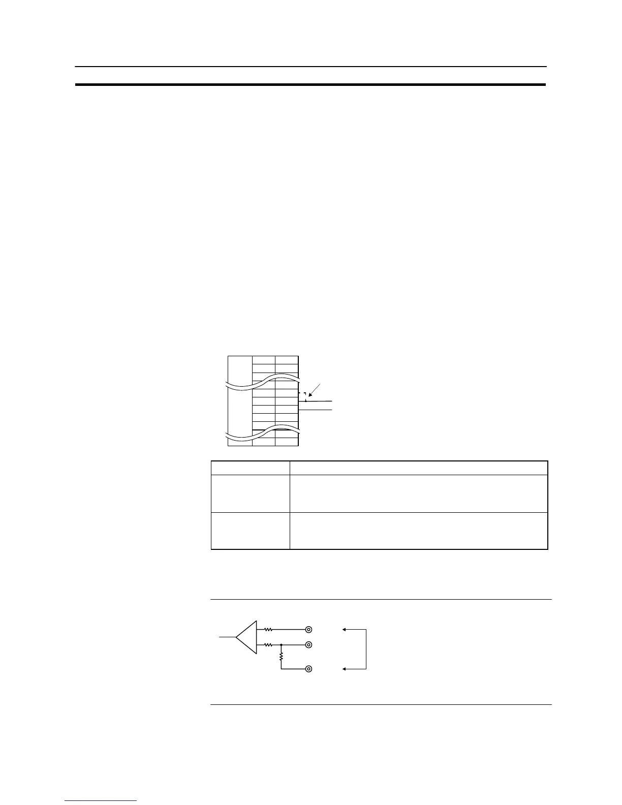
Reference - The internal circuit of the NT31/NT31C is shown below.
16 (RDA)
9 (TRM)
10 (RDB)
+
−
Terminal resistor (120 Ω)
Making a connection here inserts a terminator between
+ (RDB) and − (RDA).
- For details on setting the terminal resistance of the host unit, refer to “Setting
methods” for each type of the communication.

 Loading...


