48
Using a Memory Unit (NT31/NT31C with V1)
Section 3-5
3-5-2 Method of Use
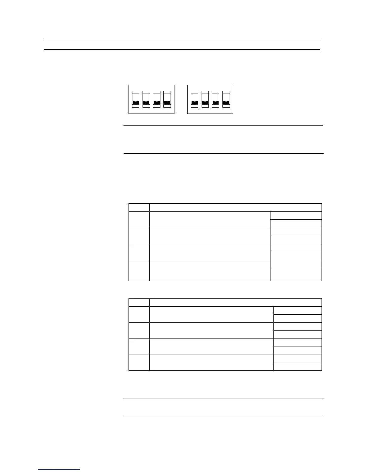
As shown in the figure below, a memory unit has two sets of four DIP switches, and
the operation is determined by the DIP switches that are set at startup.
OFF
3
SW1 SW2
OFF
4432211
Factory setting is turned all to off.
Note Always confirm that the power to the NT31/NT31C is off before setting the DIP
switches.
- Do not touch the PCB (printed circuit board) directly with bare hands.
DIP Switch Functions
The functions of the DIP switches on the memory unit are indicated in the table
below.
S SW1
Switch Function
Automatic transmission (writing from the memory
OFF: Not executed
SW1-1
Automatic transmission (writing from the memory
unit to the PT)
ON : Executed
Automatic transmission (writing from the PT to the
OFF: Not executed
SW1-2
Automatic transmission (writing from the PT to the
memory unit)
ON : Executed
Manual transmission (Direction of transmission and
OFF: Not executed
SW1-3
Manual transmission (Direction of transmission and
bank used selected at the PT touch panel)
ON : Executed
OFF: Screen data
SW1-4 Data type to transfer
ON : System
program
S SW2
Switch Function
OFF: Disable
SW2-1 Disable/enable writing to PT
ON : Enable
OFF: Disable
SW2-2 Disable/enable writing to the memory unit
ON : Enable
OFF: Bank 0
SW2-3 Area (bank) selection of automatic transmission. *
ON : Bank 1
OFF: Disable
SW2-4 System/Screen simultaneous transmission
ON : Enable
* The memory unit stores system program or screen data for one PT in each of
areas (bank 0, bank 1). (The total data storage is for two PTs.) SW2-3 sets which
of these two banks is used for automatic transmission.
Reference - The DIP switch function of the memory unit is supplemented to NT31/NT31C
With V1.

 Loading...


