40
Installation
Section 3-1
S Power supply
The applicable power supply specifications are as follows.
Item Value
Power supply 24 VDC
Allowable power supply voltage fluctuation range 20.4 VDC to 26.4 VDC
(24 VDC –15%, +10%)
Power supply voltage capacity 15 W or more
S Parts used for connection
Note For the connection to the power supply terminal block, twisted wires of 2 mm
2
or
greater cross sectional area and M3.5 size crimp terminals must be used.
Tighten the screws on the terminal block to a torque of 0.8 N⋅m.
Fork type Round type
7 mm or less 7 mm or less
- Recommended terminals
Maker
Type
(fork type)
Type
(round type)
Applicable Wire
(stranded wire)
Japan Solderless Terminal MFG 2-YS3A 2-3.5
Fuji Terminal 2-YAS3.5 V2-S3.5
2.0 to 2.63 mm
2
Nichifu Terminal 2Y-3.5 2-3.5
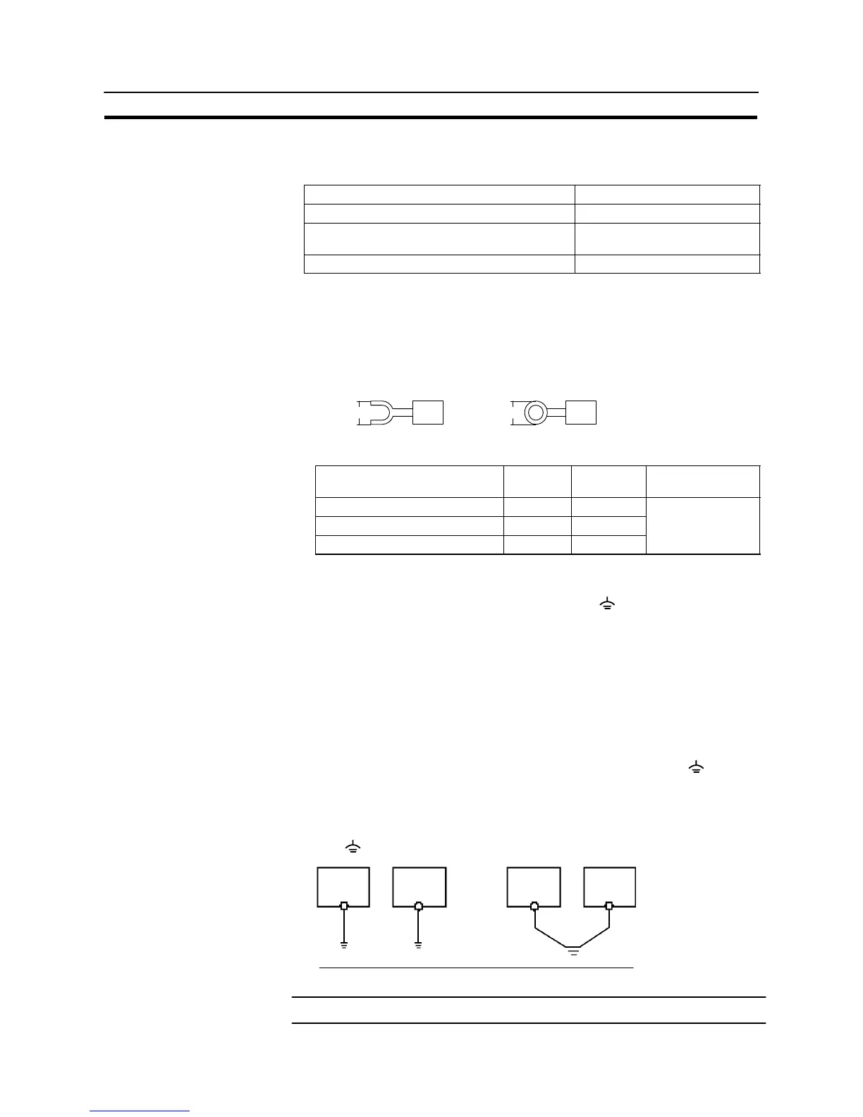
3-1-4 Grounding
The NT31/NT31C has a functional ground terminal ( ).
Carry out wiring under the following conditions.
(1) In cases where the distance between the NT31/NT31C is small and it is as-
sumed that there is no potential difference between grounds, ground as
shown in Fig. (a) below.
(2) In cases where there is a potential difference between the grounds of the
NT31/NT31C and the host, ground as shown in Fig. (b). If there is some dis-
tance between the NT31/NT31C and host and grounding at a single point is
difficult, do not connect the functional ground terminal ( ) of the
NT31/NT31C.
(3) If the NT31/NT31C is installed in the same panel as equipment that generates
noise, such as a motor or inverter, do not ground the functional ground termi-
nal ( ) of the NT31/NT31C.
Fig. (a) Fig. (b)
Class 3
grounding
a single point
Grounding at
NT31/
NT31C
Host
NT31/
NT31C
Host
Notice Carry out grounding correctly in order to prevent misoperation due to noise.

 Loading...


