198 Rockwell Automation Publication 7000L-UM301F-EN-P - March 2020
Chapter 4 Commissioning
If a device or snubber component is found to be damaged, it must be replaced
using the detailed procedures in Component Definition and Maintenance.
SGCT Anode-to-Cathode Resistance
Performing an Anode-to-Cathode resistance test not only tests the integrity of
the SGCT but also the integrity of the sharing resistor. An abnormal device
resistance measurement will indicate either a shorted device or damaged sharing
resistor.
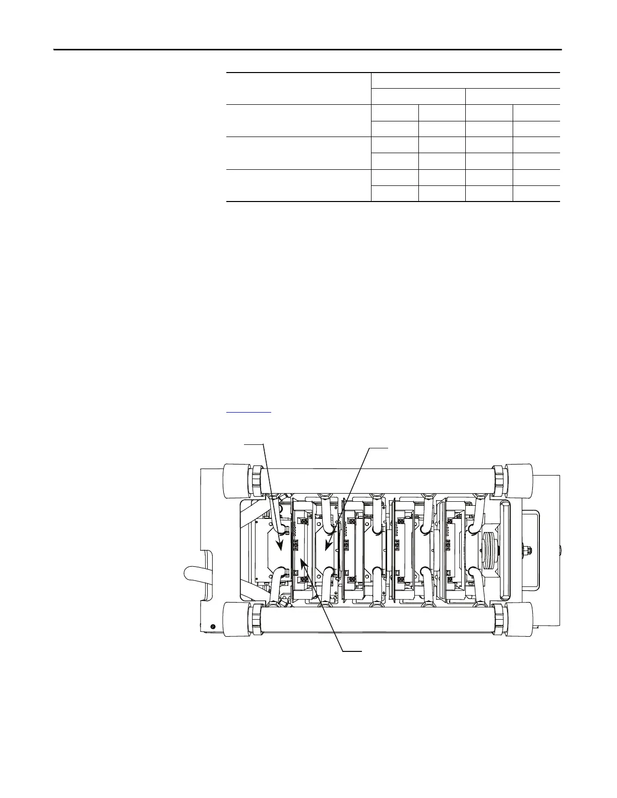
Using an ohmmeter, measure the anode-to-cathode resistance each SGCT,
looking for similar resistance values across each device. Easy access from the
anode-to-cathode is available by going from chill block to chill block as shown in
Figure 182
:
Figure 182 - Anode-to-Cathode Resistance Test Points
An SGCT when not gated on is an open circuit. A healthy device resistance value
should be close to the value-sharing resistor, however due to parallel resistances in
the firing card, the resistance value will be slightly lower.
SGCT Resistance Measurement Measured Resistance
Inverter Rectifier (AFE only)
SGCT Anode-Cathode Resistance
(Heatsink to Heatsink) k-Ω
(Lowest) (Highest) (Lowest) (Highest)
Snubber Resistance
(Test Point – Heatsink above) Ω
(Lowest) (Highest) (Lowest) (Highest)
Snubber Capacitance
(Test Point – Heatsink on Right) μF
(Lowest) (Highest) (Lowest) (Highest)
Cathode Chill Block
Anode Chill Block

 Loading...


