258 Rockwell Automation Publication 7000L-UM301F-EN-P - March 2020
Chapter 4 Commissioning
DC Current Test
Perform DC Test. Refer to the commissioning section of the PowerFlex 7000
user manual for a more detailed procedure.
Summary:
1. Make sure the Diagnostic Trend has been setup and is armed.
2. Run the DC Test with Idc Command Test (P119) set to 0.1pu. Increase
Idc Command Test from 0.1
→ 0.3pu (for AFE drives) or from
0.1
→ 0.7pu (for 18 Pulse drives) in steps of 0.1pu. At each step, verify
DC link current regulation by monitoring Idc Error (P323) and Alpha
Line (P327).
3. Capture DC link voltage waveform at ACB test point “Vd cr 1 ” and DC
link current waveform at ACB test point “Idc1” at 0.3pu (for AFE drives)
or at 0.7pu (for 18 Pulse drives).
4. Label the waveforms as “Vdcr1”, and “Idc1”.
5. Save the worksheet as “DC Test @ 0.3pu” (for AFE drives) or “DC Test @
0.7pu” (for 18 Pulse drives).
Table 15 - Oscilloscope Setting
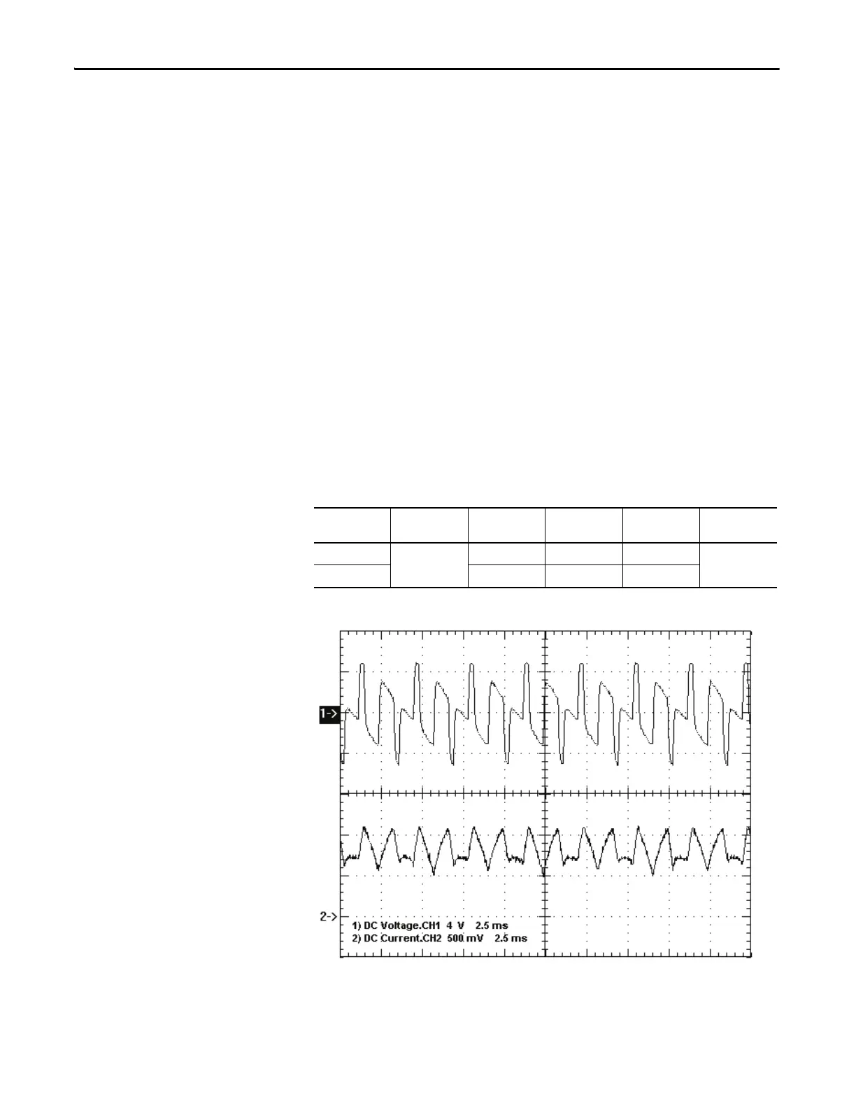
Figure 215 - Sample Waveforms:
Sample waveforms of DC Test recorded on a AFE Drive
Idc Cmd Test = 0.2pu [Ch1- Vdcr1 (yellow) Ch2 – Idc1 (blue) at ACB test points]
Oscilloscope Time Base Waveform Test-Point Waveform
Label
Sheet Name
Ch. 1 2ms/div. DC Link Voltage Vdcr1 Vdcr1 DC Test
Ch. 2 DC Link Current Idc1 Idc1

 Loading...


