218 Rockwell Automation Publication 7000L-UM301F-EN-P - March 2020
Chapter 4 Commissioning
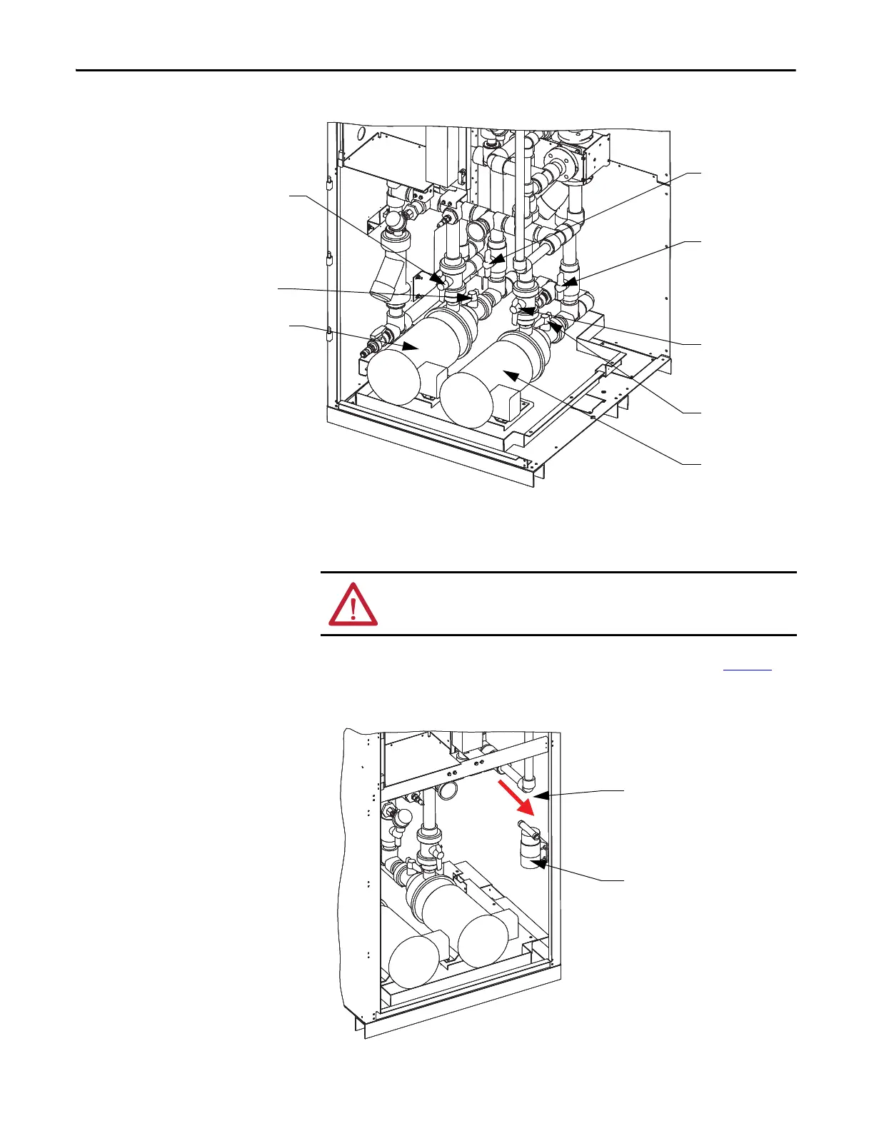
Figure 198 - Cooling Cabinet Overview showing Valve Locations – 2
System Fill and Air Venting
1. Attach transfer pump to drain/fill line (see drain/fill pump in Figure 2).
Ensure flow arrow on pump is in correct direction.
Figure 199 - Drain/Fill Pump
V11
V4
Pump 1
Pump 2
V5
V12
V3
V1
WARNING: Do not allow main pumps P1 and P2 to turn when dry. Damage to
seals can result.
Flow Direction
Transfer Pump

 Loading...


