232 Rockwell Automation Publication 7000L-UM301F-EN-P - March 2020
Chapter 4 Commissioning
– Compare the voltage feedback from all 9 test points in the ACB board
to ensure proper phasing.
Failure to perform the recommended tests will result in poor drive performance
and may result in drive converter damage.
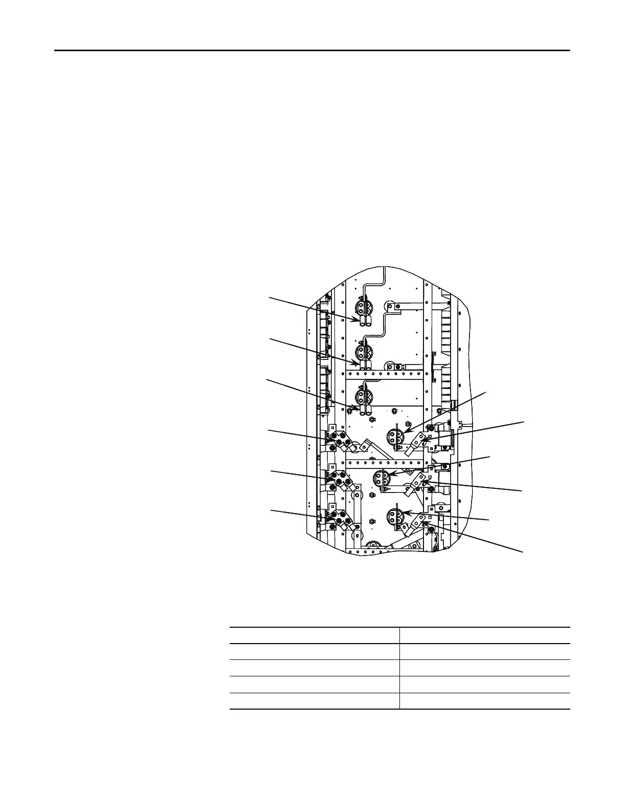
Line Terminal Resistance Measurements
Measuring the resistance between the drive line cable terminals will quickly
identify if there is interwiring between the 0°, +20°, and -20° bridges in the
isolation transformer.
Figure 204 - 18 Pulse Terminals
There are low resistances between phases through a transformer winding and a
high resistance between transformer windings. Therefore, the expected resistance
measurements are listed in the table below:
If the measurement results are not as described above, the interwiring between
the isolation transformer and drive needs to be re-inspected.
Terminal Measurement Points Expected Resistance
2U
→ 2V → 2W Approximately 0
3U → 3V → 3W Approximately 0
4U → 4V → 4W Approximately 0
#U
→ #V → #W Approximately ∞
2U
3U
4U
3V
4V
4W
3W
2V
2W
U
V
W
2U
3U
4U
3V
4V
4W
3W
2V
2W
U
V
W

 Loading...


