Rockwell Automation Publication 7000L-UM301F-EN-P - March 2020 399
Component Definition and Maintenance Chapter 5
Printing (Uploading) Control
Data
In PowerFlex 7000 drives with ForGe control, a specific memory location has
been set aside to capture and store critical data in the event of a fault condition.
This data is referred to as "Control Data". There are total 8 buffers where the data
is stored sequentially on first-in first-out basis, which ensures the data of 8 most
recent faults is always available. The data can be retrieved for analysis.
The method of retrieving Control Data is explained below.
Required:
• Laptop with Windows HyperTerminal program
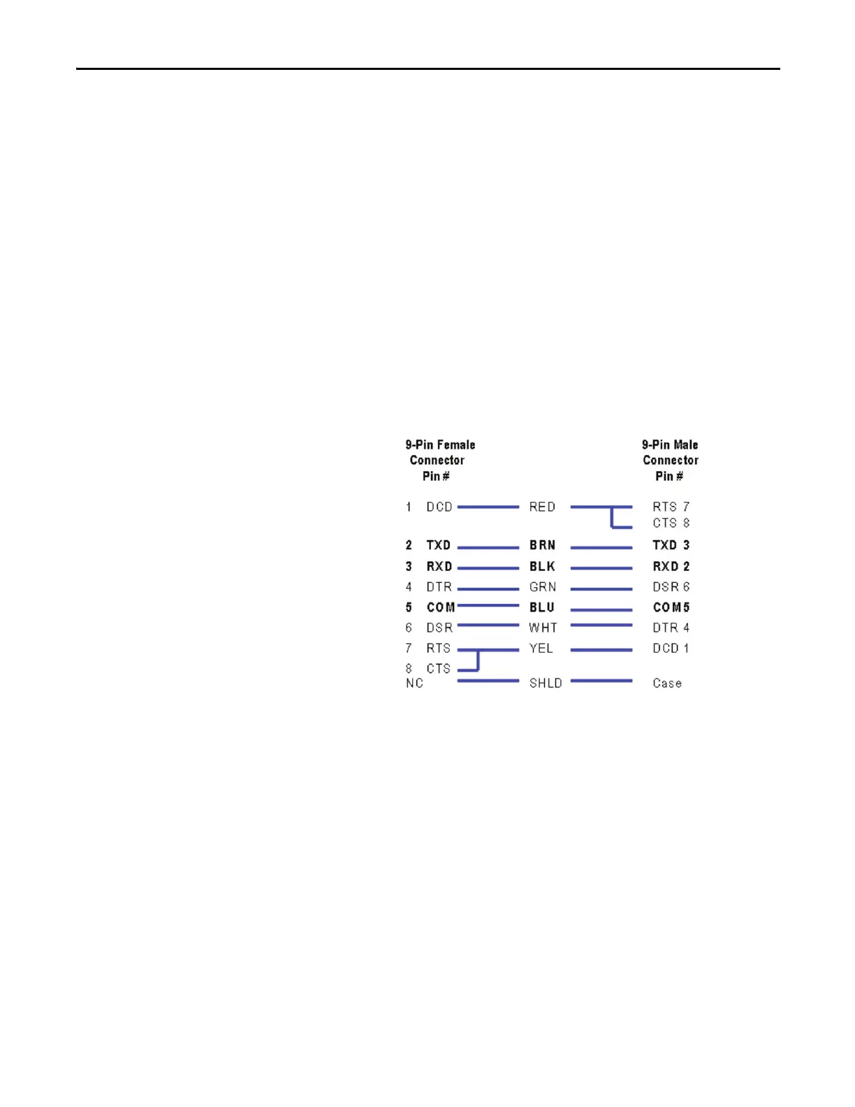
• A null-modem cable with a 9-pin female connector for the laptop serial
port, and a 9-pin male connector for Drive Processor Module (DPM) data
port (J4).
(A serial cable with pins 2-3 swapped at one end will also work)
Here is a typical pin out of a complete null-modem cable. Essentially, only 3 pins
(2, 3 and 5) are all that is required.
Figure 346 - Complete Null-Modem Cable
Connect your laptop to the drive using a 9-pin null-modem cable to DPM data
port (J4).

 Loading...


