EasyManuals Logo
Home>Rockwell Automation>DC Drives>Allen-Bradley PowerFlex 7000

Rockwell Automation Allen-Bradley PowerFlex 7000 User Manual

Rockwell Automation Allen-Bradley PowerFlex 7000
434 pages
To Next Page IconTo Next Page
To Previous Page IconTo Previous Page
Page #47 background imageLoading...
Page #47 background image
Rockwell Automation Publication 7000L-UM301F-EN-P - March 2020 47
Drive Installation Chapter 2
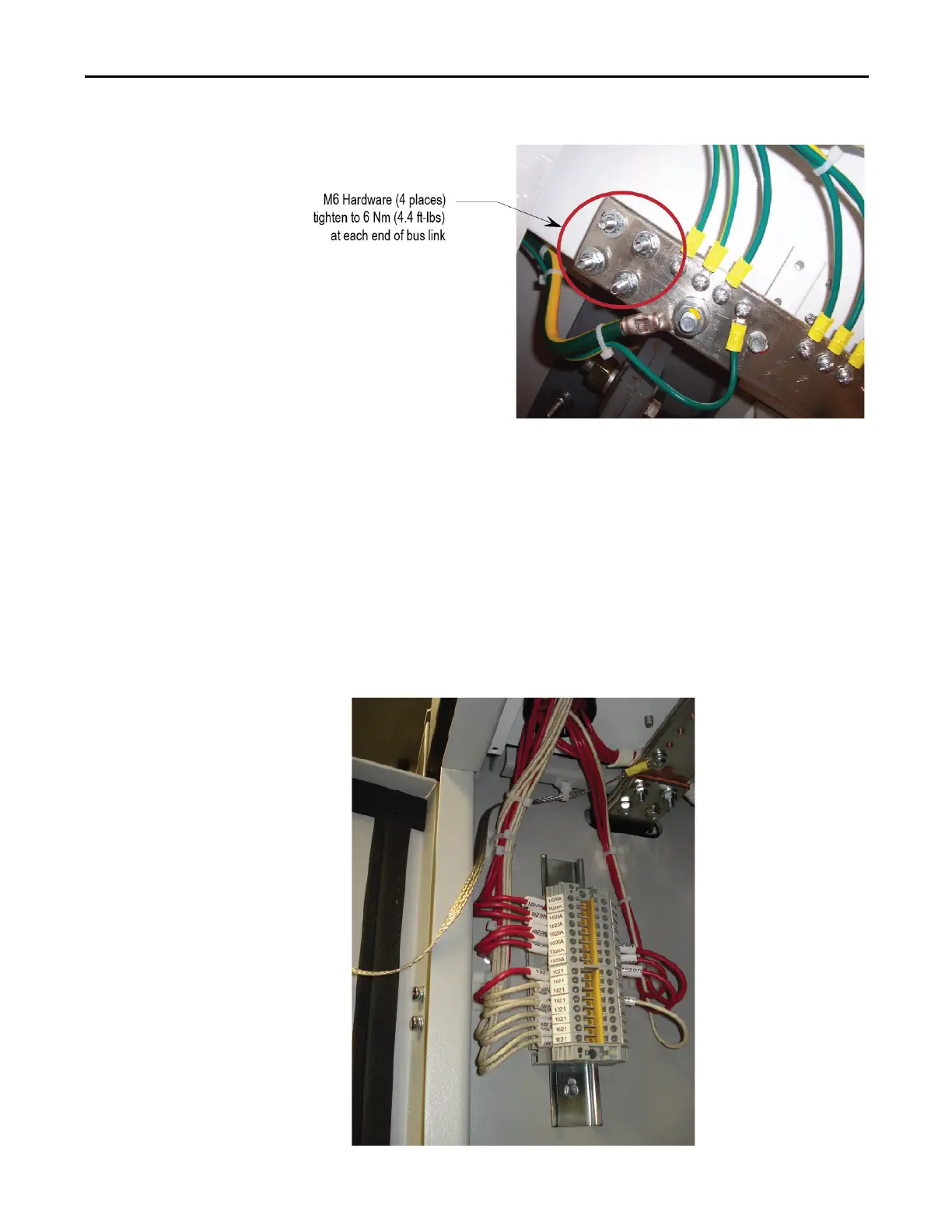
Figure 29 - Ground Bus Connection Points
(Install Ground Bus Link using Supplied Hardware)
Control Wiring Connections
Refer to EDs and wiring diagrams supplied with Drive. Contact Rockwell
Automation representative for assistance. Final wiring connections to be
performed by Rockwell Automation field service representative.
1. Remove the wireway covers located on top of the line and motor filter
capacitor sections and the DC Link section.
2. If drive has strip heater wiring, it will be coiled up in the top wireway.
Route these wires down through the grommeted cutout for connection on
the terminal blocks located in the upper left side of the capacitor section.
Figure 30 - Strip heater terminal block

Table of Contents

Other manuals for Rockwell Automation Allen-Bradley PowerFlex 7000

Questions and Answers:

Question and Answer IconNeed help?

Do you have a question about the Rockwell Automation Allen-Bradley PowerFlex 7000 and is the answer not in the manual?

Rockwell Automation Allen-Bradley PowerFlex 7000 Specifications

General IconGeneral
BrandRockwell Automation
ModelAllen-Bradley PowerFlex 7000
CategoryDC Drives
LanguageEnglish

Related product manuals